
Page 158 - Aircraft Stuctures for Engineering Student
P. 158
142 Bending of thin plates
Two types of solution are obtainable for thin plate bending problems by the applica-
tion of the principle of the stationary value of the total potential energy of the plate
and its external loading. The first, in which the form of the deflected shape of the plate
is known, produces an exact solution; the second, the Rayleigh-Ritz method, assumes
an approximate deflected shape in the form of a series having a finite number of terms
chosen to satisfy the boundary conditions of the problem and also to give the kind of
deflection pattern expected.
In Chapter 4 we saw that the total potential energy of a structural system comprised
the internal or strain energy of the structural member, plus the potential energy of the
applied loading. We now proceed to derive expressions for these quantities for the
loading cases considered in the preceding sections.
5.6.1 Strain energy produced by bending and twisting
In thin plate analysis we are concerned with deflections normal to the loaded surface
of the plate. These, as in the case of slender beams, are assumed to be primarily due to
bending action so that the effects of shear strain and shortening or stretching of the
middle plane of the plate are ignored. Therefore, it is sufficient for us to calculate
the strain energy produced by bending and twisting only as this will be applicable,
for the reason of the above assumption, to all loading cases. It must be remembered
that we are only neglecting the contributions of shear and direct strains on the deflec-
tion of the plate; the stresses producing them must not be ignored.
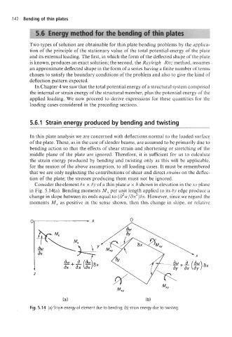
Consider the element Sx x Sy of a thin plate a x b shown in elevation in the xz plane
in Fig. 5.14(a). Bending moments M, per unit length applied to its Sy edge produce a
change in slope between its ends equal to (d2w/dx2)6x. However, since we regard the
moments M, as positive in the sense shown, then this change in slope, or relative
U 0-
dw \
ax
-+- a yj a
aw
-sx
ax
t t ax ax ax +- sx
z z
(a) (b)
Fig. 5.14 (a) Strain energy of element due to bending; (b) strain energy due to twisting.