
Page 195 - Aircraft Stuctures for Engineering Student
P. 195
6.1 1 Failure stress in plates and stiffened panels 179
Angle Tube T -section Cruciform
I
L
Basic section g = 4 cuts+ a flanges g = 3 flanges g = 4 flanges
g=2 = 12
g = 1 cut + 6 flanges = 7 g = 1 cut + 4 flanges = 5
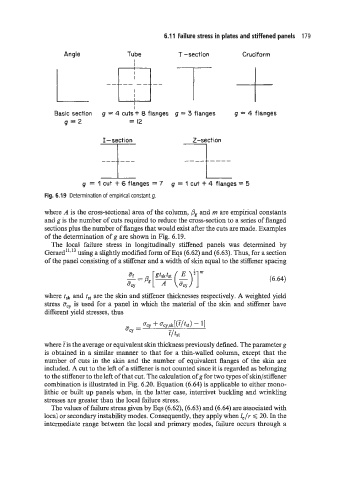
Fig. 6.19 Determination of empirical constant g.
where A is the cross-sectional area of the column, Pg and m are empirical constants
and g is the number of cuts required to reduce the cross-section to a series of flanged
sections plus the number of flanges that would exist after the cuts are made. Examples
of the determination of g are shown in Fig. 6.19.
The local failure stress in longitudinally stiffened panels was determined by
Gerard":I3 using a slightly modified form of Eqs (6.62) and (6.63). Thus, for a section
of the panel consisting of a stiffener and a width of skin equal to the stiffener spacing
(6.64)
where tsk and tSt are the skin and stiffener thicknesses respectively. A weighted yield
stress I?,, is used for a panel in which the material of the skin and stiffener have
different yield stresses, thus
where tis the average or equivalent skin thickness previously defined. The parameter g
is obtained in a similar manner to that for a thin-walled column, except that the
number of cuts in the skin and the number of equivalent flanges of the skin are
included. A cut to the left of a stiffener is not counted since it is regarded as belonging
to the stiffener to the left of that cut. The calculation of g for two types of skin/stiffener
combination is illustrated in Fig. 6.20. Equation (6.64) is applicable to either mono-
lithic or built up panels when, in the latter case, interrivet buckling and wrinkling
stresses are greater than the local failure stress.
The values of failure stress given by Eqs (6.62), (6.63) and (6.64) are associated with
local or secondary instability modes. Consequently, they apply when IJr < 20. In the
intermediate range between the local and primary modes, failure occurs through a