
Page 201 - Aircraft Stuctures for Engineering Student
P. 201
6.1 2 Flexural-torsional buckling of thin-walled columns 185
0 P - ~EIJL~ -Pxs
P - ~EI,,JL~ 0 PYS =O (6.86)
PYS - Pxs IOPIA - .rr2ET/L2 - GJ
d’v
EI, 7 = - PV (6.87)
dz-
d2 u
EI,,,, = -Pu (6.88)
d48 P d28
d24 (
El?-- GJ-Io- A)G= (6.89)
Equations (6.87), (6.88) and (6.89), unlike Eqs (6.74), (6.75) and (6.83), are uncoupled
and provide three separate values of buckling load. Thus, Eqs (6.87) and (6.88) give
values for the Euler buckling loads about the x and y axes respectively, while Eq.
(6.89) gives the axial load which would produce pure torsional buckling; clearly the
buckling load of the column is the lowest of these values. For the column whose
buckled shape is defined by Eqs (6.84), substitution for v, u and 6’ in Eqs (6.87),
(6.88) and (6.89) respectively gives
Example 6.1
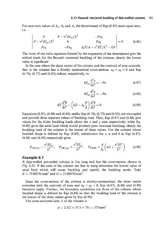
A thin-walled pin-ended column is 2m long and has the cross-section shown in
Fig. 6.22. If the ends of the column are free to warp determine the lowest value of
axial load which will cause buckling and specify the buckling mode. Take
E = 75 000 N/mm2 and G = 21 000 N/mm2.
Since the cross-section of the column is doubly-symmetrical, the shear centre
coincides with the centroid of area and xs = ys = 0; Eqs (6.87), (6.88) and (6.89)
therefore apply. Further, the boundary conditions are those of the column whose
buckled shape is defined by Eqs (6.84) so that the buckling load of the column is
the lowest of the three values given by Eqs (6.90).
The cross-sectional area A of the column is
A = 2.5(2 x 37.5f75) = 375mm’