
Page 205 - Aircraft Stuctures for Engineering Student
P. 205
6.1 3 Tension field beams 189
6.1 3.1 Complete diagonal tension
is--- _.__*___- Ylll
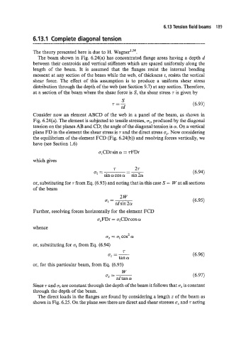
The theory presented here is due to H. Wagner'"4.
The beam shown in Fig. 6.24(a) has concentrated flange areas having a depth d
between their centroids and vertical stiffeners which are spaced uniformly along the
length of the beam. It is assumed that the flanges resist the internal bending
moment at any section of the beam while the web, of thickness t, resists the vertical
shear force. The effect of this assumption is to produce a uniform shear stress
distribution through the depth of the web (see Section 9.7) at any section. Therefore,
at a section of the beam where the shear force is S, the shear stress r is given by
S
r=- (6.93)
td
Consider now an element ABCD of the web in a panel of the beam, as shown in
Fig. 6.24(a). The element is subjected to tensile stresses, at, produced by the diagonal
tension on the planes AB and CD; the angle of the diagonal tension is a. On a vertical
plane FD in the element the shear stress is r and the direct stress a,. Now considering
the equilibrium of the element FCD (Fig. 6.24(b)) and resolving forces vertically, we
have (see Section 1.6)
a,CDt sin a = TFDt
which gives
a, = 7 - 27 (6.94)
-
sin a cos a sin 2a
or, substituting for r from Eq. (6.93) and noting that in this case S = W at all sections
of the beam
2w
a, = (6.95)
td sin 2a
Further, resolving forces horizontally for the element FCD
azFDt = atCDt cos a
whence
a, = a, cos- a
7
or, substituting for at from Eq. (6.94)
r
a, = - (6.96)
tan a
or, for this particular beam, from Eq. (6.93)
W
a, = (6.97)
td tan a
~
Since T and at are constant through the depth of the beam it follows that 0; is constant
through the depth of the beam.
The direct loads in the flanges are found by considering a length z of the beam as
shown in Fig. 6.25. On the plane mm there are direct and shear stresses az and r acting