
Page 209 - Aircraft Stuctures for Engineering Student
P. 209
6.1 3 Tension field beams 193
400mm
1200 mm
-I
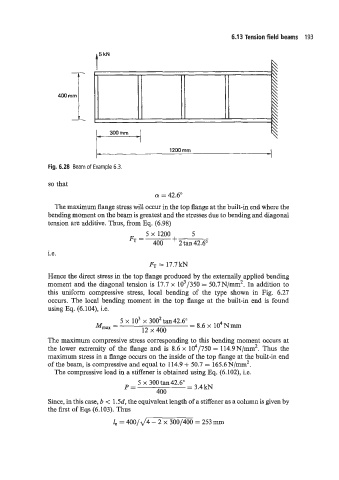
Fig. 6.28 Beam of Example 6.3.
so that
Q! = 42.6"
The maximum flange stress will occur in the top flange at the built-in end where the
bending moment on the beam is greatest and the stresses due to bending and diagonal
tension are additive. Thus, from Eq. (6.98)
5 x 1200 5
FT =
400 -k 2 tan 42.6"
i.e.
FT = 17.7 kN
Hence the direct stress in the top flange produced by the externally applied bending
moment and the diagonal tension is 17.7 x 10³/350 = 50.7N/mm2. In addition to
this uniform compressive stress, local bending of the type shown in Fig. 6.27
occurs. The local bending moment in the top flange at the built-in end is found
using Eq. (6.104), i.e.
5 x lo3 x 3002 tan42.6"
Mnax = = 8.6 x 10⁴Nmm
12 x 400
The maximum compressive stress corresponding to this bending moment occurs at
the lower extremity of the flange and is 8.6 x 10⁴/750 = 114.9N/mm2. Thus the
maximum stress in a flange occurs on the inside of the top flange at the built-in end
of the beam, is compressive and equal to 114.9 + 50.7 = 165.6N/mm2.
The compressive load in a stiffener is obtained using Eq. (6.102), i.e.
5 x 300 tan 42.6"
P= = 3.4 kN
400
Since, in this case, b < 1.5d, the equivalent length of a stiffener as a column is given by
the first of Eqs (6.103). Thus
1, = 400/d4 - 2 x 300/400 = 253 mm