
Page 211 - Aircraft Stuctures for Engineering Student
P. 211
6.13 Tension field beams 195
shear stress TCR is given by the empirical expression
( ;R)
k = tanh 0.5log- (6.1 11)
The ratio r/rcR is known as the loading ratio or buckling stress ratio. The buckling
stress TCR may be calculated from the formula
(6.1 12)
where k,, is the coefficient for a plate with simply supported edges and & and Rb are
empirical restraint coefficients for the vertical and horizontal edges of the web panel
respectively. Graphs giving k,,, Rd and Rb are reproduced in Kuhn14.
The stress equations (6.106) and (6.107) are modified in the light of these assump-
tions and may be rewritten in terms of the applied shear stress r as
kr cot a
(TF (6.113)
(2A,/td) + 0.5(1 - k)
kr tan a
(Ts = (6.114)
(As/tb) + 0.5( 1 - k)
Further, the web stress ut given by Eq. (6.94) becomes two direct stresses: crl along the
direction of a given by
2kr
(TI =- + r(l - k) sin2a (6.115)
sin 2a
and CQ perpendicular to this direction given by
a, = -r(1 - k) sin2a (6.116)
The secondary bending moment of Eq. (6.104) is multiplied by the factor k, while the
effective lengths for the calculation of stiffener buckling loads become (see Eqs
(6.103))
I, = d,/Jl + k2(3 - 2b/d,) for b < 1.5d
or
I, = d, for b > 1%
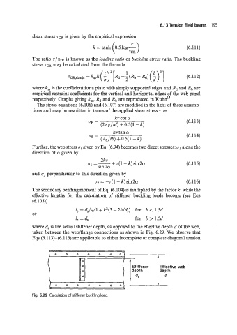
where d, is the actual stiffener depth, as opposed to the effective depth d of the web,
taken between the web/flange connections as shown in Fig. 6.29. We observe that
Eqs (6.1 13)-(6.116) are applicable to either incomplete or complete diagonal tension
0 0 0 0 0 0 0
St if fener Effective web
depth depth
d
_-
Fig. 6.29 Calculation of stiffener buckling load.