
Page 208 - Aircraft Stuctures for Engineering Student
P. 208
192 Structural instability
at a stiffener and is given by
uytb 2
MmaX =-
12
or, substituting for gy from Eq. (6.101)
wb2 tan a
Mmax = 12d (6.104)
Midway between the stiffeners this bending moment reduces to Wb2 tan a/24d.
The angle a adjusts itself such that the total strain energy of the beam is a minimum.
If it is assumed that the flanges and stiffeners are rigid then the strain energy comprises
the shear strain energy of the web only and a = 45". In practice, both flanges and
stiffeners deform so that a is somewhat less than 45", usually of the order of 40"
and, in the type of beam common to aircraft structures, rarely below 38". For
beams having all components made of the same material the condition of minimum
strain energy leads to various equivalent expressions for Q, one of which is
2
tan a=- Ot +'F (6.105)
ut + %
in which uF and as are the uniform direct compressive stresses induced by the diagonal
tension in the flanges and stiffeners respectively. Thus, from the second term on the
right-hand side of either of Eqs (6.98) or (6.99)
W
CF = (6.106)
2AF tan a
in which AF is the cross-sectional area of each flange. Also, from Eq. (6.102)
wb
us = -tana (6.107)
ASd
where As is the cross-sectional area of a stiffener. Substitution of at from Eq. (6.95)
and oF and crs from Eqs (6.106) and (6.107) into Eq. (6.105), produces an equation
which may be solved for a. An alternative expression for a, again derived from a
consideration of the total strain energy of the beam, is
(6.108)
Example 6.3
The beam shown in Fig. 6.28 is assumed to have a complete tension field web. If the
cross-sectional areas of the flanges and stiffeners are, respectively, 350mm2 and
300mm2 and the elastic section modulus of each flange is 750mm3, determine the
maximum stress in a flange and also whether or not the stiffeners will buckle. The
thickness of the web is 2mm and the second moment of area of a stiffener about
an axis in the plane of the web is 2000 mm4; E = 70 000 N/mm2.
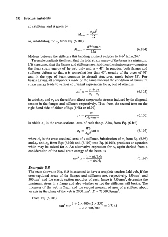
From Eq. (6.108)
1 +2 x 400/(2 x 350)
4
tan a= = 0.7143
1 + 2 x 300/300