
Page 207 - Aircraft Stuctures for Engineering Student
P. 207
6.13 Tension field beams 191
From a consideration of the vertical equilibrium of the element HDC we have
ayHCt = a,CDt sin a
which gives
2
au = a, sin a
Substituting for at from Eq. (6.94)
aJ = Ttana! (6.100)
or, from Eq. (6.93) in which S = W
W
a,, = -tan a (6.101)
. td
The tensile stresses a,, on horizontal planes in the web of the beam cause compression
in the vertical stiffeners. Each stiffener may be assumed to support half of each
adjacent panel in the beam so that the compressive load P in a stiffener is given by
P = a,tb
which becomes, from Eq. (6.101)
Wb
P =--ana (6.102)
d
If the load P is sufficiently high the stiffeners will buckle. Tests indicate that they
buckle as columns of equivalent length
I, = d/dm forb < 1.5d
or (6.103)
I, = d for b > 1.5d
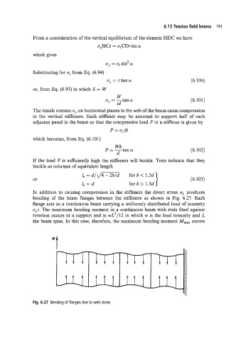
In addition to causing compression in the stiffeners the direct stress a,, produces
bending of the beam flanges between the stiffeners as shown in Fig. 6.27. Each
flange acts as a continuous beam carrying a uniformly distributed load of intensity
aut. The maximum bending moment in a continuous beam with ends fixed against
rotation occurs at a support and is wL2/12 in which w is the load intensity and L
the beam span. In this case, therefore, the maximum bending moment M,,, occurs
Fig. 6.27 Bending of flanges due to web stress.