
Page 313 - Aircraft Stuctures for Engineering Student
P. 313
294 Open and closed, thin-walled beams
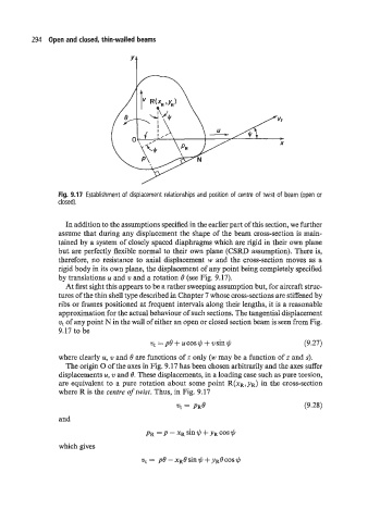
Fig. 9.17 Establishment of displacement relationships and position of centre of twist of beam (open or
closed).
In addition to the assumptions specijied in the earlier part of this section, we further
assume that during any displacement the shape of the beam cross-section is main-
tained by a system of closely spaced diaphragms which are rigid in their own plane
but are perfectly flexible normal to their own plane (CSRD assumption). There is,
therefore, no resistance to axial displacement w and the cross-section moves as a
rigid body in its own plane, the displacement of any point being completely specified
by translations u and 21 and a rotation 6 (see Fig. 9.17).
At first sight this appears to be a rather sweeping assumption but, for aircraft struc-
tures of the thin shell type described in Chapter 7 whose cross-sections are stiffened by
ribs or frames positioned at frequent intervals along their lengths, it is a reasonable
approximation for the actual behaviour of such sections. The tangential displacement
vt of any point N in the wall of either an open or closed section beam is seen from Fig.
9.17 to be
v, = p6 + ucos $ + vsin $ (9.27)
where clearly u, w and B are functions of z only (w may be a function of z and s).
The origin 0 of the axes in Fig. 9.17 has been chosen arbitrarily and the axes suffer
displacements u, w and 0. These displacements, in a loading case such as pure torsion,
are equivalent to a pure rotation about some point R(xR,YR) in the cross-section
where R is the centre of twist. Thus, in Fig. 9.17
(9.28)
and
pR = p - xR sin 1(, + yR cos $
which gives