
Page 317 - Aircraft Stuctures for Engineering Student
P. 317
298 Open and closed, thin-walled beams
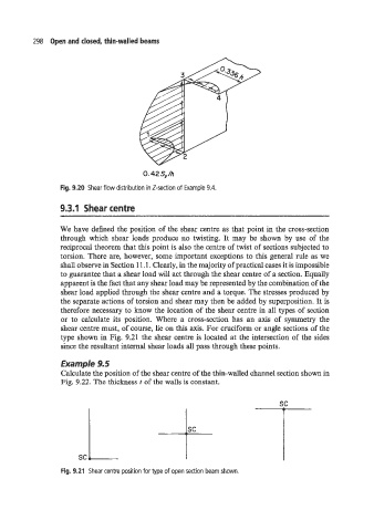
0.42 S,/h
Fig. 9.20 Shear flow distribution in Z-section of Example 9.4.
9.3.1 Shear centre
We have defined the position of the shear centre as that point in the cross-section
through which shear loads produce no twisting. It may be shown by use of the
reciprocal theorem that this point is also the centre of twist of sections subjected to
torsion. There are, however, some important exceptions to this general rule as we
shall observe in Section 1 1.1. Clearly, in the majority of practical cases it is impossible
to guarantee that a shear load will act through the shear centre of a section. Equally
apparent is the fact that any shear load may be represented by the combination of the
shear load applied through the shear centre and a torque. The stresses produced by
the separate actions of torsion and shear may then be added by superposition. It is
therefore necessary to know the location of the shear centre in all types of section
or to calculate its position. Where a cross-section has an axis of symmetry the
shear centre must, of course, lie on this axis. For cruciform or angle sections of the
type shown in Fig. 9.21 the shear centre is located at the intersection of the sides
since the resultant internal shear loads all pass through these points.
Example 9.5
Calculate the position of the shear centre of the thin-walled channel section shown in
Fig. 9.22. The thickness t of the walls is constant. sc
sc I+
Fig. 9.21 Shear centre position for type of open section beam shown.