
Page 385 - Aircraft Stuctures for Engineering Student
P. 385
366 Stress analysis of aircraft components
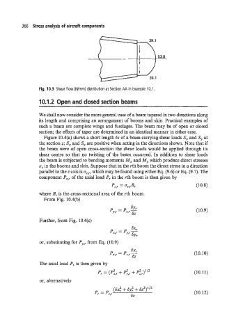
53.8
Fig. 10.3 Shear flow (N/mm) distribution at Section AA in Example 10.1
10.1.2 Open and closed section beams
We shall now consider the more general case of a beam tapered in two directions along
its length and comprising an arrangement of booms and skin. Practical examples of
such a beam are complete wings and fuselages. The beam may be of open or closed
section; the effects of taper are determined in an identical manner in either case.
Figure 10.4(a) shows a short length 6z of a beam carrying shear loads S, and Sy at
the section z; Sx and Sy are positive when acting in the directions shown. Note that if
the beam were of open cross-section the shear loads would be applied through its
shear centre so that no twisting of the beam occurred. In addition to shear loads
the beam is subjected to bending moments Mx and My which produce direct stresses
a, in the booms and skin. Suppose that in the rth boom the direct stress in a direction
parallel to the z axis is ai,r, which may be found using either Eq. (9.6) or Eq. (9.7). The
component P,:, of the axial load P, in the rth boom is then given by
Pqr = ai,rBr (10.8)
where B, is the cross-sectional area of the rth boom.
From Fig. 10.4(b)
(10.9)
Further, from Fig. 10.4(c)
or, substituting for Py,, from Eq. (10.9)
(10.10)
The axial load Pr is then given by
Pr = + p',r + pI,r)1'2 (10.11)
or, alternatively
(10.12)