Page 389 - Aircraft Stuctures for Engineering Student
P. 389
370  Stress analysis of aircraft components

                  From column @


                  From column @


                  From column @


                  From Eqs (10.15)
                                     Sx,w = 0,  Sy,w = 100 - 33.4 = 66.6 kN

                  The shear flow distribution in the walls of the beam is now found using the method
                  described in Section 9.9. Since, for this beam, Zxy  = 0 and Sx = Sx,w = 0, Eq. (9.80)
                  reduces to


                  We now  ‘cut’ one of  the walls, say  16. The resulting ‘open section’ shear flow is
                  given by
                                                  66.6 x IO3
                                           qb = -             BrYr
                                                  5.4 x  108   r=l

                  or


                  Thus
                              qb.16 =
                              qb.12 = 0 - 1.23 X   X 900 X 300 = -33.2N/mm

                              qb,23 = -33.2  - 1.23 x   x 1200 x 300 = -77.5N/mm
                              qb,34 = -77.5  - 1.23 x   x 900 x 300 = -110.7N/mm
                              qb.45 = -77.5  N/mm  (from symmetry)
                              qb,56 = -33.2  N/mm  (from symmetry)

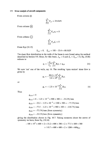
                   giving the  distribution  shown in  Fig.  10.7.  Taking moments about  the  centre of
                   symmetry we have, from Eq. (10.16)
                           -100  x  lo3 x 600 = 2 x 33.2 x 600 x 300 + 2 x 77.5 x 600 x 300

                                             + 110.7 x 600 x 600 + 2 x 1200 x 600qs,0

