
Page 388 - Aircraft Stuctures for Engineering Student
P. 388
10.1 Tapered beams 369
booms and the shear flow distribution in the walls at a section 2m from the built-in
end if the booms resist all the direct stresses while the walls are effective only in shear.
Each corner boom has a cross-sectional area of 900mm2 while both central booms
have cross-sectional areas of 1200 mm'.
The internal force system at a section 2 m from the built-in end of the beam is
S,. = 100kN, S, = 0, M, = -100 x 2 = -200kNm, My = 0
The beam has a doubly symmetrical cross-section so that I&, = 0 and Eq. (9.6)
reduces to
MXY
gz = -
IXX
in which, for the beam section shown in Fig. 10.6(b)
4
x
=
lYX 900 x 300' + 2 x 1200 x 3002 = 5.4 x lo8 IIIITI~
Then
-200 x lo6
gz,r =
5.4 x 10⁹ Yr
or
u~!~ -0.37~~ (ii)
=
Hence
P,,, = -0.37yrBr (iii)
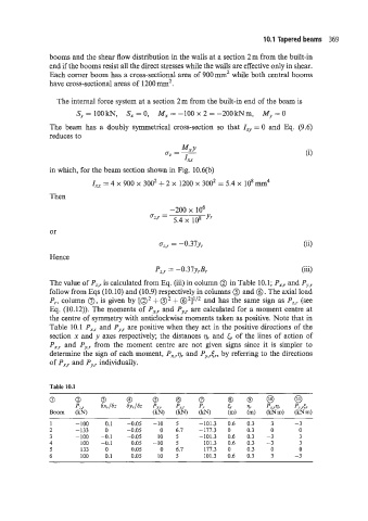
The value of Pz,r is calculated from Eq. (iii) in column 0 in Table 10.1; P,,, and Pv>r
The
follow from Eqs (10.10) and (10.9) respectively in columns @ and 0. axial load
P,., column 0, given by [a2 + @' + @2]1/2 and has the same sign as P,:, (see
is
Eq. (10.12)). The moments of PX,r and Py,r are calculated for a moment centre at
the centre of symmetry with anticlockwise moments taken as positive. Note that in
Table 10.1 Px>, and P,,,r are positive when they act in the positive directions of the
section x and y axes respectively; the distances qr and & of the lines of action of
Px:r and P,,,, from the moment centre are not given signs since it is simpler to
determine the sign of each moment, PX.,q, and PJ3&, by referring to the directions
of P,, and Py., individually.
Table 10.1
0 0 0 @ @ @ a a @ @ 0
Pz, 6x,/6r 6y,lSz Px,r Py,, P,. 5, rlr Px,Jr P?&
Boom (kN) (kN) (kN) (kN) (m) (m) (kNm) (kNm)
1 -100 0.1 -0.05 -10 5 -101.3 0.6 0.3 3 -3
2 -133 0 -0.05 0 6.7 -177.3 0 0.3 0 0
3 -100 -0.1 -0.05 10 5 -101.3 0.6 0.3 -3 3
4 100 -0.1 0.05 -10 5 101.3 0.6 0.3 -3 3
5 133 0 0.05 0 6.7 177.3 0 0.3 0 0
6 100 0.1 0.05 IO 5 101.3 0.6 0.3 3 -3