
Page 390 - Aircraft Stuctures for Engineering Student
P. 390
Izll 10.1 Tapered beams 371
77.5
33.2
110.7
i
6
4
77.5
33.2
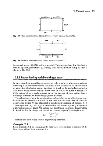
Fig. 10.7 'Open section'shear flow (Wmm) distribution in beam section of Example 10.2.
Fig. 10.8 Shear flow (Wrnm) distribution in beam section of Example 10.2.
from which qs,O = -97.0 N/mm (Le. clockwise). The complete shear flow distribution
is found by adding the value of qs,o to the qb shear flow distribution of Fig. 10.7 and is
shown in Fig. 10.8.
10.1.3 Beams having variable stringer areas
*
w=l"--=lp_: -I____ --u- - . - = - 1
In many aircraft, structural beams, such as wings, have stringers whose cross-sectional
areas vary in the spanwise direction. The effects of this variation on the determination
of shear flow distribution cannot therefore be found by the methods described in
Section 9.9 which assume constant boom areas. In fact, as we noted in Section 9.9,
if the stringer stress is made constant by varying the area of cross-section there is
no change in shear flow as the stringer/boom is crossed.
The calculation of shear flow distributions in beams having variable stringer areas
is based on the alternative method for the calculation of shear flow distributions
described in Section 9.9 and illustrated in the alternative solution of Example 9.13.
The stringer loads Pz., and P_,,J are calculated at two sections z1 and z2 of the beam
a convenient distance apart. We assume that the stringer load varies linearly along
its length so that the change in stringer load per unit length of beam is given by
The shear flow distribution follows as previously described.
Example 10.3
Solve Example 10.2 by considering the differences in boom load at sections of the
beam either side of the specified section.