
Page 394 - Aircraft Stuctures for Engineering Student
P. 394
10.2 Fuselages 375
10.2.1 Bending
The skin/stringer arrangement is idealized into one comprising booms and skin as
described in Section 9.9. The direct stress in each boom is then calculated using
either Eq. (9.6) or Eq. (9.7) in which the reference axes and the section properties
refer to the direct stress carrying areas of the cross-section.
Example 10.4
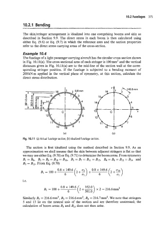
The fuselage of a light passenger carrying aircraft has the circular cross-section shown
in Fig. 10.11(a). The cross-sectional area of each stringer is 100mm2 and the vertical
distances given in Fig. 10.1 l(a) are to the mid-line of the section wall at the corre-
sponding stringer position. If the fuselage is subjected to a bending moment of
200 kNm applied in the vertical plane of symmetry, at this section, calculate the
direct stress distribution.
(a)
Fig. 10.1 1 (a) Actual fuselage section; (b) idealized fuselage section.
The section is first idealized using the method described in Section 9.9. As an
approximation we shall assume that the skin between adjacent stringers is flat so that
we may use either Eq. (9.70) or Eq. (9.71) to determine the boom areas. From symmetry
B1 Bg, Bz = Bg = Blo = B16, B3 = B7 = B11 = B15, B4 = B6 = Blz = B14 and
B5 = BI3. From Eq. (9.70)
0.8 x 149.6 (2 + :) + 0.8 X 149.6 ( ;;)
B1 = loo+ 2+-
6 6
i.e.
B1 = 100 + Oa8 149.6 ( 2+- ;if::) x 2 = 216.6mm2
6
Similarly B2 = 216.6mm2, B3 = 216.6mm2, B4 = 216.7mm2. We note that stringers
5 and 13 lie on the neutral axis of the section and are therefore unstressed; the
calculation of boom areas B5 and B13 does not then arise.