
Page 396 - Aircraft Stuctures for Engineering Student
P. 396
10.2 Fuselages 377
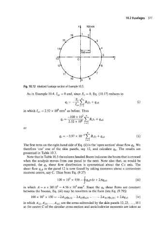
Fig. 10.12 Idealized fuselage section of Example 10.5.
As in Example 10.4, Ixy = 0 and, since S, = 0, Eq. (10.17) reduces to
in which = 2.52 x 10' mm4 as before. Thus
-100 x io3
"' 2.52 x 10' BrYr + 4s.o
r=l
or
n
qs = -3.97 x Bry, + qs,o (ii)
r=l
The first term on the right-hand side of Eq. (ii) is the 'open section' shear flow qb. We
therefore 'cut' one of the skin panels, say 12, and calculate qb. The results are
presented in Table 10.3.
Note that in Table 10.3 the column headed Boom indicates the boom that is crossed
when the analysis moves from one panel to the next. Note also that, as would be
expected, the qb shear flow distribution is symmetrical about the Cx axis. The
shear flow q,s,o in the panel 12 is now found by taking moments about a convenient
moment centre, say C. Thus from Eq. (9.37)
f
100 x IO3 x 150 = qbpds+2Aq,v.o (iii)
in which A = T x 381.02 = 4.56 x 105mm2. Since the qb shear flows are constant
between the booms, Eq. (iii) may be rewritten in the form (see Eq. (9.79))
100 x io3 x 150 = -2A17qb,12 - 2A23qb.23 - .' ' - 2A16 lqb.16 I + 2Aqy:O (iv)
in which AI2; . . A161 are the areas subtended by the skin panels 12: 23,. . . , 16 1
at the centre C of the circular cross-section and anticlockwise moments are taken as