
Page 395 - Aircraft Stuctures for Engineering Student
P. 395
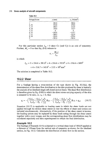
376  Stress analysis of aircraft components

                             Table 10.2


                             1                       381.0            302.4
                             2,  16                  352.0            279.4
                             3,  15                  269.5            213.9
                             4,  14                  145.8            115.7
                             5,  13                   0                 0
                             6,  12                 -145.8           -115.7
                             7,  11                 -269.5           -213.9
                             8,  10                 -352.0           -279.4
                             9                      -381.0           -302.4


                   For  this  particular  section Zxy = 0  since Cx  (and  Cy) is  an  axis of  symmetry.
                 Further, My = 0 so  that Eq. (9.6) reduces to


                 in which
                         Zxx = 2 x 216.6 x 381.02 + 4 x 216.6 x 352.02 + 4 x 216.6 x 26952

                               + 4 x 216.7 x 145.82 = 2.52  x  lo8 mm4
                 The solution is completed in Table 10.2.


                  10.2.2  Shear


                 For  a  fuselage  having  a  cross-section  of  the  type  shown  in  Fig.  lO.ll(a),  the
                 determination of the shear flow distribution in the skin produced by shear is basically
                 the analysis  of an idealized single cell closed section beam. The shear flow distribution
                 is therefore given by Eq. (9.80) in which the direct stress carrying capacity of the skin
                 is assumed to be zero, i.e. tD = 0, thus


                  Equation  (10.17) is  applicable to loading cases in which the  shear loads are not
                 applied through the section shear centre so that the effects of shear and torsion are
                 included simultaneously. Alternatively, if the position of the shear centre is known,
                 the loading system may be replaced by shear loads acting through the shear centre
                  together with a pure torque, and the corresponding shear flow distributions may be
                  calculated separately and then superimposed to obtain the final distribution.

                  Example 10.5
                  The fuselage of Example 10.4 is subjected to a vertical shear load of 100 kN applied at
                  a distance of 150 mm from the vertical axis of symmetry as shown, for the idealized
                 section, in Fig. 10.12. Calculate the distribution of shear flow in the section.