
Page 398 - Aircraft Stuctures for Engineering Student
P. 398
10.2 Fuselages 379
be checked by calculating the resultant of the shear flow distribution parallel to the Cy
axis. Thus
2[(98.8 + 66.0)145.8 + (86.3 + 53.51123.7 + (63.1 + 30.3)82.5 + (32.8 - 0)29.0]
x lop3 = 99.96 kN
which agrees with the applied shear load of 100 kN. The analysis of a fuselage which is
tapered along its length is carried out using the method described in Section 10.1 and
illustrated in Example 10.2.
10.2.3 Torsion
A fuselage section is basically a single cell closed section beam. The shear flow
distribution produced by a pure torque is therefore given by Eq. (9.49) and is
T
q=- (10.18)
2A
It is immaterial whether or not the section has been idealized since, in both cases, the
booms are assumed not to carry shear stresses.
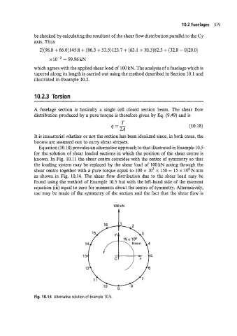
Equation (10.18) provides an alternative approach to that illustrated in Example 10.5
for the solution of shear loaded sections in which the position of the shear centre is
known. In Fig. 10.11 the shear centre coincides with the centre of symmetry so that
the loading system may be replaced by the shear load of 100 kN acting through the
shear centre together with a pure torque equal to 100 x lo3 x 150 = 15 x lo6 Nmm
as shown in Fig. 1C.14. The shear flow distribution due to the shear load may be
found using the method of Example 10.5 but with the left-hand side of the moment
equation (iii) equal to zero for moments about the centre of symmetry. Alternatively,
use may be made of the symmetry of the section and the fact that the shear flow is
100 kN
I
Fig. 10.14 Alternative solution of Example 10.5.