
Page 465 - Aircraft Stuctures for Engineering Student
P. 465
446 Structural constraint
At the built-in end, aw/as is zero and hence
(11.1)
in which de/&, du/dz and dw/dz are the unknowns, the remaining terms being
functions of the section geometry.
The resultants of the internal shear flows q must be statically equivalent to the
applied loading, so that
f 1
qcos$ds = S,
I
qsinqds = S, (11.2)
Substitution for q from Eq. (1 1.1) in Eqs (1 1.2) yields
E 1 tp cos $ ds + tcos @ sin $ ds = -
dz dz G
(11.3)
dz dz
dv dz f
tpcos$ds+- tpsin$ds= G
Equations (1 1.3) are solved simultaneously for dO/dz, du/dz and dw/dz. These values
are then substituted in Eq. (1 1.1) to obtain the shear flow, and hence the shear stress
distribution.
Attention must be paid to the signs of $, p and q in Eqs (1 1.3). Positive directions for
each parameter are suggested in Fig. 11.1 although alternative conventions may be
adopted. In general, however, there are rules which must be obeyed, these having
special importance in the solution of multicell beams. Briefly, these are as follows. The
positive directions of q and s are the same but may be assigned arbitrarily in each wall.
Then p is positive if movement of the foot of the perpendicular along the positive
direction of the tangent leads to an anticlockwise rotation of p about 0. $ is the
clockwise rotation of the tangent vector necessary to bring it into coincidence with
the positive direction of the x axis.
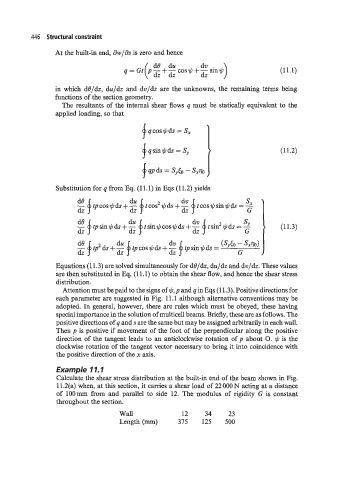
Example 11. I
Calculate the shear stress distribution at the built-in end of the beam shown in Fig.
11.2(a) when, at this section, it carries a shear load of 22 000 N acting at a distance
of lOOmm from and parallel to side 12. The modulus of rigidity G is constant
throughout the section.
Wall 12 34 23
Length (mm) 375 125 500