
Page 466 - Aircraft Stuctures for Engineering Student
P. 466
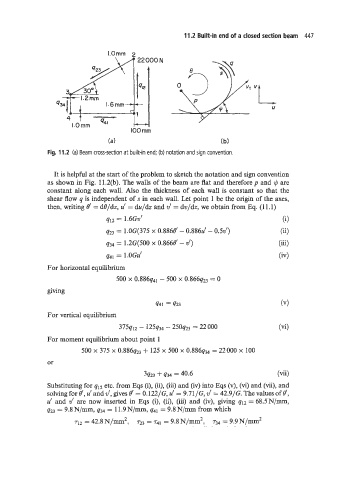
11.2 Built-in end of a closed section beam  447

                                 I.Ornm  2
                                          22 000 N


                                                                             vL


                             -                                                    U
                                 1.6rnrn
                     4
                       1.0 rnrn
                                        100 rnrn
                                 (a)                               (b)
               Fig. 11.2  (a) Beam cross-section at built-in end; (b) notation and sign convention.


                 It is helpful at the start of the problem to sketch the notation and sign convention
               as shown in Fig.  11.2(b). The walls of the beam are flat and therefore p  and $J  are
               constant  along each wall. Also the thickness of each wall is constant  so that the
               shear flow q is independent of s in each wall. Let point  1 be the origin of the axes,
               then, writing 13‘  = dO/dz, u’  = du/&  and v‘  = dv/dz, we obtain from Eq. (1 1.1)
                                 q12  = 1.6Gv’                                       (i)
                                 q23  = i.o~(m 0.8868’ - 0.886~’ - 0.5~’)           (E)
                                              x
                                 q34  = i.2~poo 0.866e’ - .~r)                      (iii)
                                              x
                                 q41  = 1.OGu’                                      (4
               For horizontal equilibrium
                                    500 x 0.886q41 - 500 x O.866q23 = 0
               giving

                                               q41  = q23
               For vertical equilibrium
                                    375q12 - 125q34 - 25oq23 = 22 000
               For moment equilibrium about point 1
                         500 x 375 x 0.886q23 + 125 x 500 x 0.886q34 = 22000 x 100
               or

                                            3q23 + q34 = 40.6                       (vii)
               Substituting for qlz etc. from Eqs (i), (ii), (iii) and (iv) into Eqs (v), (vi) and (vii), and
               solving for 8‘, u‘ alid v’,  gives 8‘  = 0.122/G, u‘  = 9.71/G, v‘  = 42.9/G. The values of#,
               u’  and  v’  are now  inserted in  Eqs (i), (ii),  (iii) and  (iv), giving qI2 = 68.5N/mm,
               q23 = 9.8 N/mm, q34  = 11.9 N/mm, q41  = 9.8 N/mm from which
                       q2 = 42.8 N/mm2,   ~23 = 7-41  = 9.8 N/mm2:  r34 = 9.9 N/mm2