
Page 467 - Aircraft Stuctures for Engineering Student
P. 467
448 Structural constraint
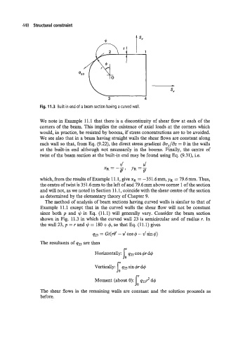
Fig. 11.3 Built-in end of a beam section having a curved wall.
We note in Example 11.1 that there is a discontinuity of shear flow at each of the
corners of the beam. This implies the existence of axial loads at the corners which
would, in practice, be resisted by booms, if stress concentrations are to be avoided.
We see also that in a beam having straight walls the shear flows are constant along
each wall so that, from Eq. (9.22), the direct stress gradient ao,/az = 0 in the walls
at the built-in end although not necessarily in the booms. Finally, the centre of
twist of the beam section at the built-in end may be found using Eq. (9.31), i.e.
V’ U’
XR = -- gl YR=Y
which, from the results of Example 11.1, givexR = -351.6mmYyR = 79.6mm. Thus,
the centre of twist is 351.6 mm to the left of and 79.6 mm above corner 1 of the section
and will not, as we noted in Section 1 1.1 , coincide with the shear centre of the section
as determined by the elementary theory of Chapter 9.
The method of analysis of beam sections having curved walls is similar to that of
Example 11.1 except that in the curved walls the shear flow will not be constant
since both p and q$ in Eq. (11.1) will generally vary. Consider the beam section
shown in Fig. 11.3 in which the curved wall 23 is semicircular and of radius r. In
the wall 23, p = r and q$ = 180 + 4, so that Eq. (11.1) gives
q23 = Gt(rf3‘ - u’ cos q5 - v’ sin q5)
The resultants of q23 are then
Horizontally: 1: 423 cos 4r dq5
Vertically: 423 sin 4r dq5
Moment (about 0): j: q23r2 dq5
The shear flows in the remaining walls are constant and the solution proceeds as
before.