
Page 480 - Aircraft Stuctures for Engineering Student
P. 480
11.4 Shear lag 461
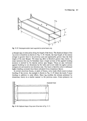
Fig. 11.17 Rectangular section beam supported at corner booms only.
q changes sign at some point along the length of the beam. The displaced shape of the
top cover is therefore as shown in Fig. 11.18. Clearly, the final length of the central
stringer is greater than in the previous case and appreciably greater than the final
length of the spar flanges. The shear lag effect is therefore greater than before. In
some instances this may be beneficial since a larger portion of the applied bending
moment is resisted by the heavier section spar flanges. These are also restrained
against buckling in two directions by the webs and covers while the lighter section
stringers are restrained in one direction only. The beam is therefore able to withstand
higher bending moments than those calculated from elementary theory.
In certain situations beams, or parts of beams, carry loads which cause in-plane
bending of the covers. An example is shown in Fig. 11.19 where the loads P cause
bending in addition to axial effects. Shear lag modifies the stresses predicted by
elementary theory in a similar manner to the previous cases. From symmetry we
Displaced shape
I
I I
I
\
1
I
I
I
I
I
Fig. 11.18 Displaced shape of top cover of box team of Fig. 11 .I 7.