
Page 481 - Aircraft Stuctures for Engineering Student
P. 481
462 Structural constraint
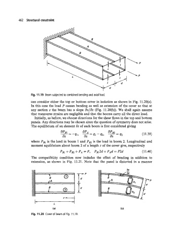
Fig. 11.19 Beam subjected to combined bending and axial load.
can consider either the top or bottom cover in isolation as shown in Fig. 11.2O(a).
In this case the load P causes bending as well as extension of the cover so that at
any section z the beam has a slope dv/& (Fig. 11.20(b)). We shall again assume
that transverse strains are negligible and that the booms carry all the direct load.
Initially, as before, we choose directions for the shear flows in the top and bottom
panels. Any directions may be chosen since the question of symmetry does not arise.
The equilibrium of an element Sz of each boom is first considered giving
-- - -41, apA - 41 -42, r= (1 1.39)
aPBl
aPB2
--
42
dZ az
where PSI is the load in boom 1 and PBz is the load in boom 2. Longitudinal and
moment equilibrium about boom 2 of a length z of the cover give, respectively
+ Pm PA = P, P~12d + PAd = P2d (1 1.40)
The compatibility condition now includes the effect of bending in addition to
extension, as shown in Fig. 11.21. Note that the panel is distorted in a manner
\ 1
B 0"f
/A
B
2
I- L I
(a)
Fig. 11.20 Coverof beamof Fig. 11.19.