
Page 486 - Aircraft Stuctures for Engineering Student
P. 486
11.5 Constraint of open section beams 467
tY
z
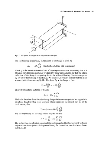
Fig. 11 25 Torsion of I-section beam fully built-in at one end.
and the bending moment MF in the plane of the flange is given by
d2u
MF = -EIF - (see Section 9.1 for sign convention)
dz2
where I, is the second moment of area of theflange cross-section about they axis. It is
assumed here that displacements produced by shear are negligible so that the lateral
deflection of the flange is completely due to the self-equilibrating direct stress system
c7r set up by the bending of the flange. We shall not, however, assume that the shear
stresses in the flange are negligible. The shear S, in the flange is then
d3 u
dMF -
SF =-- -EIFT
dz dz
or substituting for u in terms of 8 and h
h d38
SF = -EIF - -
2 dz3
Similarly, there is a shear force in the top flange of the same magnitude but opposite in
direction. Together they form a couple which represents the second part Tr of the
total torque, thus
and the expression for the total torque may be written
de h2 d38
T = GJ-- EIF - 7
dz 2 dz
The insight into the physical aspects of the problem gained in the above will be found
helpful in the development of the general theory for the arbitrary section beam shown
in Fig. 11.26.