
Page 485 - Aircraft Stuctures for Engineering Student
P. 485
466 Structural constraint
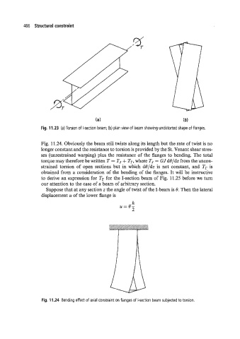
Fig. 11.23 (a) Torsion of I-section beam; (b) plan view of beam showing undistorted shape of flanges.
Fig. 11.24. Obviously the beam still twists along its length but the rate of twist is no
longer constant and the resistance to torsion is provided by the St. Venant shear stres-
ses (unrestrained warping) plus the resistance of the flanges to bending. The total
torque may therefore be written T = TJ + Tr, where TJ = GJ d8/dz from the uncon-
strained torsion of open sections but in which d8/dz is not constant, and Tr is
obtained from a consideration of the bending of the flanges. It will be instructive
to derive an expression for Tr for the I-section beam of Fig. 11.25 before we turn
our attention to the case of a beam of arbitrary section.
Suppose that at any section z the angle of twist of the I-beam is 8. Then the lateral
displacement u of the lower flange is
h
U=8-
2
Fig. 11.24 Bending effect of axial constraint on flanges of I-section beam subjected to torsion.