
Page 484 - Aircraft Stuctures for Engineering Student
P. 484
11.5 Constraint of open section beams 465
Finally, the shear flow distributions are obtained from Eqs (1 1.39), thus
-dPBI - PAX sinh X(L - z)
41 =- dz - 2(2B+A) coshXL (1 1.52)
aPB2 - -PAX sinh X(L - z)
q2=-- dz 2(2B+A) coshXL (1 1.53)
Again we see that each expression for direct stress, Eqs (1 1.47), (11.49) and (1 1.51),
comprises a term which gives the solution from elementary theory together with a
correction for the shear lag effect. The shear flows q1 and q2 are self-equilibrating,
as can be seen from Eqs (1 1.52) and (1 1.53), and are entirely produced by the shear
lag effect (ql and q2 must be self-equilibrating since no shear loads are applied).
LcllllllrrrJrwr- I
11.5 Constraint of open section beams
Instances of open section beams occurring in isolation are infrequent in aircraft
structures. The majority of wing structures do, however, contain cut-outs for
undercarriages, inspection panels and the like, so that at these sections the wing is
virtually an open section beam. We saw in Chapter 10 that one method of analysis
for such cases is to regard the applied torque as being resisted by the differential
bending of the front and rear spars in the cut-out bay. An alternative approach is
to consider the cut-out bay as an open section beam built-in at each end and subjected
to a torque. We shall now investigate the method of analysis of such beams.
If such a beam is axially unconstrained and loaded by a pure torque T the rate of
twist is constant along the beam and is given by
d0
T = GJ- (from Eq. (9.59))
dz
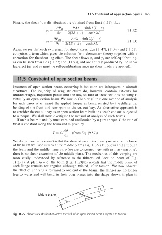
We also showed in Section 9.6 that the shear stress varies linearly across the thickness
of the beam wall and is zero at the middle plane (Fig. 11.22). It follows that although
the beam and the middle plane warp (we are concerned here with primary warping),
there is no shear distortion of the middle plane. The mechanics of this warping are
more easily understood by reference to the thin-walled I-section beam of Fig.
11.23(a). A plan view of the beam (Fig. 11.23(b)) reveals that the middle plane of
each flange remains rectangular, although twisted, after torsion. We now observe
the effect of applying a restraint to one end of the beam. The flanges are no longer
free to warp and will bend in their own planes into the shape shown in plan in
@--
Middle plane
Fig. 11.22 Shear stress distribution across the wall of an open section beam subjected to torsion.