
Page 130 - Algorithm Collections for Digital Signal Processing Applications using MATLAB
P. 130
118 Chapter 3
Consider any vector in the space can also be represented as the linear
combination of Wavelet basis as described below. Note that orthonormal
basis
w1= (1/sqrt(8)) [1 1 1 1 1 1 1 1] T
w2= (1/sqrt(8)) [1 1 1 1 -1 -1 -1 -1] T
w3= (1/sqrt(4)) [1 1 -1 -1 0 0 0 0] T
w4= (1/sqrt(4)) [0 0 0 0 1 1 -1 -1] T
w5= (1/sqrt(2)) [1 -1 0 0 0 0 0 0] T
w6= (1/sqrt(2)) [0 0 1 -1 0 0 0 0] T
w7= (1/sqrt(2)) [0 0 0 0 1 -1 0 0] T
w8= (1/sqrt(2)) [0 0 0 0 0 0 1 -1] T
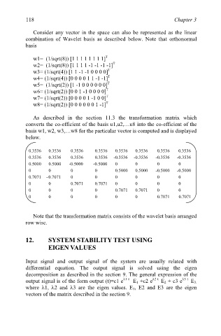
As described in the section 11.3 the transformation matrix which
converts the co-efficient of the basis u1,u2,…u8 into the co-efficient of the
basis w1, w2, w3,…w8 for the particular vector is computed and is displayed
below.
0.3536 0.3536 0.3536 0.3536 0.3536 0.3536 0.3536 0.3536
0.3536 0.3536 0.3536 0.3536 -0.3536 -0.3536 -0.3536 -0.3536
0.5000 0.5000 -0.5000 -0.5000 0 0 0 0
0 0 0 0 0.5000 0.5000 -0.5000 -0.5000
0.7071 - 0.7071 0 0 0 0 0 0
0 0 0.7071 0.7071 0 0 0 0
0 0 0 0 0.7071 0.7071 0 0
0 0 0 0 0 0 0.7071 0.7071
Note that the transformation matrix consists of the wavelet basis arranged
row wise.
12. SYSTEM STABILITY TEST USING
EIGEN VALUES
Input signal and output signal of the system are usually related with
differential equation. The output signal is solved using the eigen
decomposition as described in the section 9. The general expression of the
output signal is of the form output (t)=c1 e λ1 t E 1 +c2 e λ2 t E 2 + c3 e λ3 t E 3.
where λ1, λ2 and λ3 are the eigen values. E 1, E2 and E3 are the eigen
vectors of the matrix described in the section 9.