
Page 143 - Alternative Energy Systems in Building Design
P. 143
SOLAR POWER SYSTEM DESIGN CONSIDERATIONS 119
bandwidth, at which the inverter may perform power conversion within safe margins
and yield the highest conversion efficiency. Excursion of output voltage produced by
PV strings beyond the safe boundaries is determined by V mp or combined series PV
string maximum peak voltage when measured in open-circuit conditions. For instance,
11 SolarWorld PV module AG SW 175 monocrystalline cells, when connected in series
at an average ambient temperature of 90°F (V mp = 35.7 V), produce a swing voltage of
387 V, which will be within the input voltage boundaries of the inverter.
On determination of the allowed number of series PV strings, the designer will be
in a position to configure the topology of the PV array and subarrays in a manner that
will conform to inverter power input requirements.
In most instances, inverter manufacturers provide a Web-based solar array power
calculator, and the designer may use it to choose the type of inverter, its power rating,
the PV module manufacturer, and model number. By inserting these data, along with
ambient operational temperature, tilt angle, and array derating coefficient figures (as
outlined earlier), the calculations provide accurate inverter string connectivity and ac
power output performance results.
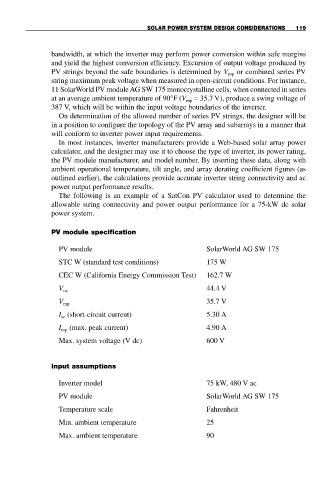
The following is an example of a SatCon PV calculator used to determine the
allowable string connectivity and power output performance for a 75-kW dc solar
power system.
PV module specification
PV module SolarWorld AG SW 175
STC W (standard test conditions) 175 W
CEC W (California Energy Commission Test) 162.7 W
V oc 44.4 V
V mp 35.7 V
I (short-circuit current) 5.30 A
sc
I mp (max. peak current) 4.90 A
Max. system voltage (V dc) 600 V
Input assumptions
Inverter model 75 kW, 480 V ac
PV module SolarWorld AG SW 175
Temperature scale Fahrenheit
Min. ambient temperature 25
Max. ambient temperature 90