
Page 144 - Alternative Energy Systems in Building Design
P. 144
120 SOLAR POWER SYSTEM PHYSICS AND TECHNOLOGIES
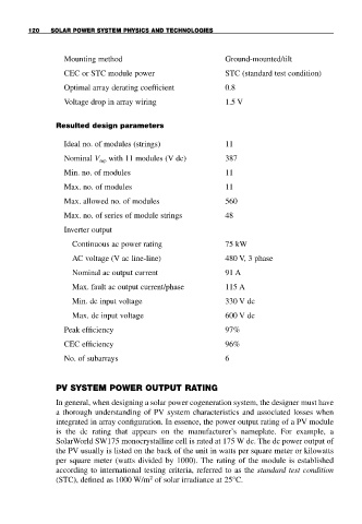
Mounting method Ground-mounted/tilt
CEC or STC module power STC (standard test condition)
Optimal array derating coefficient 0.8
Voltage drop in array wiring 1.5 V
Resulted design parameters
Ideal no. of modules (strings) 11
Nominal V mp with 11 modules (V dc) 387
Min. no. of modules 11
Max. no. of modules 11
Max. allowed no. of modules 560
Max. no. of series of module strings 48
Inverter output
Continuous ac power rating 75 kW
AC voltage (V ac line-line) 480 V, 3 phase
Nominal ac output current 91 A
Max. fault ac output current/phase 115 A
Min. dc input voltage 330 V dc
Max. dc input voltage 600 V dc
Peak efficiency 97%
CEC efficiency 96%
No. of subarrays 6
PV SYSTEM POWER OUTPUT RATING
In general, when designing a solar power cogeneration system, the designer must have
a thorough understanding of PV system characteristics and associated losses when
integrated in array configuration. In essence, the power output rating of a PV module
is the dc rating that appears on the manufacturer’s nameplate. For example, a
SolarWorld SW175 monocrystalline cell is rated at 175 W dc. The dc power output of
the PV usually is listed on the back of the unit in watts per square meter or kilowatts
per square meter (watts divided by 1000). The rating of the module is established
according to international testing criteria, referred to as the standard test condition
2
(STC), defined as 1000 W/m of solar irradiance at 25°C.