
Page 222 - Alternative Energy Systems in Building Design
P. 222
198 ENERGY CONSERVATION
ZMS Control series
Zone management system PC Controlled ZMS2000
HVAC
System
Optional
Supply Air
Temperature Sensor
Supply Air Duct and Pressure Sensor
Optional
Proportional
Zone Control Panel Motorized
Motorized Motorized Motorized Bypass Damper
Damper Damper Damper
Zone 1
Zone 32 Zone 2 Zone Temperature
Zone Temperature Zone Temperature Sensor with LCD
Sensor Sensor Display
Return Air Register
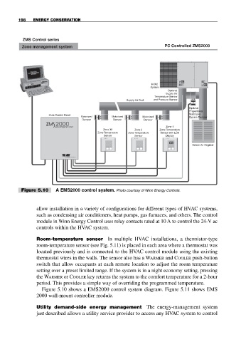
Figure 5.10 A EMS2000 control system. Photo courtesy of Winn Energy Controls.
allow installation in a variety of configurations for different types of HVAC systems,
such as condensing air conditioners, heat pumps, gas furnaces, and others. The control
module in Winn Energy Control uses relay contacts rated at 10 A to control the 24-V ac
controls within the HVAC system.
Room-temperature sensor In multiple HVAC installations, a thermistor-type
room-temperature sensor (see Fig. 5.11) is placed in each area where a thermostat was
located previously and is connected to the HVAC control module using the existing
thermostat wires in the walls. The sensor also has a WARMER and COOLER push-button
switch that allow occupants at each remote location to adjust the room temperature
setting over a preset limited range. If the system is in a night economy setting, pressing
the WARMER or COOLER key returns the system to the comfort temperature for a 2-hour
period. This provides a simple way of overriding the programmed temperature.
Figure 5.10 shows a EMS2000 control system diagram. Figure 5.11 shows EMS
2000 wall-mount controller module.
Utility demand-side energy management The energy-management system
just described allows a utility service provider to access any HVAC system to control