
Page 298 - Alternative Energy Systems in Building Design
P. 298
272 WIND ENERGY TECHNOLOGIES
s
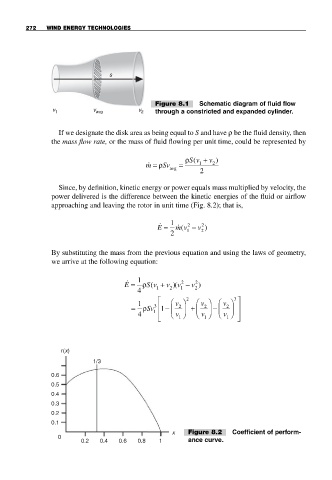
Figure 8.1 Schematic diagram of fluid flow
v 1 v avg v 2 through a constricted and expanded cylinder.
If we designate the disk area as being equal to S and have ρ be the fluid density, then
the mass flow rate, or the mass of fluid flowing per unit time, could be represented by
Sv +
ρ ( v )
& m = ρ Sv = 1 2
avg
2
Since, by definition, kinetic energy or power equals mass multiplied by velocity, the
power delivered is the difference between the kinetic energies of the fluid or airflow
approaching and leaving the rotor in unit time (Fig. 8.2); that is,
&
E = 1 & m v − v )
2
2
(
2 1 2
By substituting the mass from the previous equation and using the laws of geometry,
we arrive at the following equation:
1
&
S v +
2
2
E = ρ ( 1 v )( v − v )
2
2
1
4
⎡ 2 2 3 ⎤
1 ⎛ v ⎞ ⎛ v ⎞ ⎛ v ⎞
= ρ Sv 1 ⎢ − ⎜ 2 ⎟ + ⎜ 2 ⎟ − ⎜ 2 ⎟ ⎥
3
4 1 ⎢ ⎝ v ⎠ ⎝ v ⎠ ⎝ v ⎠ ⎥
⎣ 1 1 1 ⎦
r(x)
1/3
0.6
0.5
0.4
0.3
0.2
0.1
x Figure 8.2 Coefficient of perform-
0
0.2 0.4 0.6 0.8 1 ance curve.