
Page 95 - Alternative Energy Systems in Building Design
P. 95
SOLAR POWER SYSTEM DESIGN 71
protected with a forward-biased diode connected to the positive output of the panel (not
shown in the figure).
An appropriate surge protector connected between the positive and negative supplies
provides protection against lightning surges, which could damage system components. In
order to provide equipment-grounding bias, the chassis or enclosures of all PV modules
and the dc motor pump are tied together by means of grounding clamps. The system
ground, in turn, is connected to an appropriate grounding rod. All PV interconnecting
wires are sized, and the proper type is selected to prevent power losses caused by a
number of factors, such as exposure to the sun, excessive wire resistance, and additional
requirements that are mandated by the NEC.
This type of PV solar system is typically used in an agricultural application, where
either regular electrical service is unavailable or the cost is prohibitive. A floating or
submersible dc pump connected to a dc PV array can provide a constant stream of well
water that can be accumulated in a reservoir for farm or agricultural use. Subsequent
sections discuss the specifications and use of all system components employed in solar
power cogeneration applications.
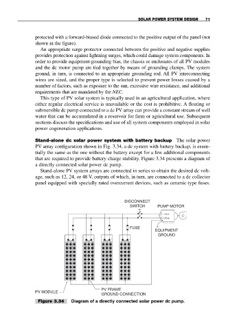
Stand-alone dc solar power system with battery backup The solar power
PV array configuration shown in Fig. 3.34, a dc system with battery backup, is essen-
tially the same as the one without the battery except for a few additional components
that are required to provide battery charge stability. Figure 3.34 presents a diagram of
a directly connected solar power dc pump.
Stand-alone PV system arrays are connected in series to obtain the desired dc volt-
age, such as 12, 24, or 48 V, outputs of which, in turn, are connected to a dc collector
panel equipped with specially rated overcurrent devices, such as ceramic-type fuses.
DISCONNECT
SWITCH PUMP MOTOR
−
+
FUSE
EQUIPMENT
GROUND
PV FRAME
PV MODULE
GROUND CONNECTION
Figure 3.34 Diagram of a directly connected solar power dc pump.