
Page 96 - Alternative Energy Systems in Building Design
P. 96
72 SOLAR POWER SYSTEM PHYSICS AND TECHNOLOGIES
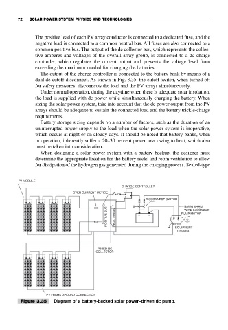
The positive lead of each PV array conductor is connected to a dedicated fuse, and the
negative lead is connected to a common neutral bus. All fuses are also connected to a
common positive bus. The output of the dc collector bus, which represents the collec-
tive amperes and voltages of the overall array group, is connected to a dc charge
controller, which regulates the current output and prevents the voltage level from
exceeding the maximum needed for charging the batteries.
The output of the charge controller is connected to the battery bank by means of a
dual dc cutoff disconnect. As shown in Fig. 3.35, the cutoff switch, when turned off
for safety measures, disconnects the load and the PV arrays simultaneously.
Under normal operation, during the daytime when there is adequate solar insolation,
the load is supplied with dc power while simultaneously charging the battery. When
sizing the solar power system, take into account that the dc power output from the PV
arrays should be adequate to sustain the connected load and the battery trickle-charge
requirements.
Battery storage sizing depends on a number of factors, such as the duration of an
uninterrupted power supply to the load when the solar power system is inoperative,
which occurs at night or on cloudy days. It should be noted that battery banks, when
in operation, inherently suffer a 20–30 percent power loss owing to heat, which also
must be taken into consideration.
When designing a solar power system with a battery backup, the designer must
determine the appropriate location for the battery racks and room ventilation to allow
for dissipation of the hydrogen gas generated during the charging process. Sealed-type
PV MODULE
CHARGE CONTROLLER
OVER CURRENT DEVICE
DISCONNECT SWITCH
+ − BAWG XHH-2
POSITIVE BUS NEGATIVE BUS + − − + PUMP MOTOR
WIRE IN CONDUIT
EQUIPMENT
GROUND
FUSED DC
COLLECTOR
PV FRAME GROUND CONNECTION
Figure 3.35 Diagram of a battery-backed solar power–driven dc pump.