
Page 97 - Alternative Energy Systems in Building Design
P. 97
SOLAR POWER SYSTEM DESIGN 73
batteries do not require special ventilation. All dc wiring calculations discussed take
into consideration losses resulting from solar exposure, battery cable current derating,
and equipment current resistance requirements, as stipulated in Article 690 in the NEC.
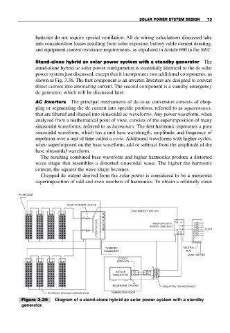
Stand-alone hybrid ac solar power system with a standby generator The
stand-alone hybrid ac solar power configuration is essentially identical to the dc solar
power system just discussed, except that it incorporates two additional components, as
shown in Fig. 3.36. The first component is an inverter. Inverters are designed to convert
direct current into alternating current. The second component is a standby emergency
dc generator, which will be discussed later.
AC Inverters The principal mechanisms of dc-to-ac conversion consists of chop-
ping or segmenting the dc current into specific portions, referred to as squarewaves,
that are filtered and shaped into sinusoidal ac waveforms. Any power waveform, when
analyzed from a mathematical point of view, consists of the superimposition of many
sinusoidal waveforms, referred to as harmonics. The first harmonic represents a pure
sinusoidal waveform, which has a unit base wavelength, amplitude, and frequency of
repetition over a unit of time called a cycle. Additional waveforms with higher cycles,
when superimposed on the base waveform, add or subtract from the amplitude of the
base sinusoidal waveform.
The resulting combined base waveform and higher harmonics produce a distorted
wave shape that resembles a distorted sinusoidal wave. The higher the harmonic
content, the squarer the wave shape becomes.
Chopped dc output derived from the solar power is considered to be a numerous
superimposition of odd and even numbers of harmonics. To obtain a relatively clean
PV MODULE
OVER CURRENT DEVICE
DISCONNECT SWITCH
+ − +
POSITIVE BUS NEGATIVE BUS EMERG. GEN INPUT H N H LOAD
INVERTER WITH
− N
FUSED DC NEUTRAL
COLLECTOR BUS
LOAD CENTER
CIRCUIT
BREAKER
H
BACKUP
GENERATOR
N
EQUIPMENT GROUND ISOLATION TRANSFORMER
GENERATOR ROOM
PV FRAME GROUND CONNECTION
Figure 3.36 Diagram of a stand-alone hybrid ac solar power system with a standby
generator.