
Page 99 - Alternative Energy Systems in Building Design
P. 99
SOLAR POWER SYSTEM DESIGN 75
In all instances, solar power design engineers must ensure that all chassis of equip-
ment and PV arrays, including stanchions and pedestals, are connected together via
appropriate grounding conductors that are connected to a single-point service ground
bus bar, usually located within the vicinity of the main electrical service switchgear.
In grid-connected systems, switching of ac power from the standby generator and the
inverter to the service bus or the connected load is accomplished by internal or external
automatic transfer switches.
Standby power generators always must comply with the NEC requirements outlined
in the following articles:
■ Electrical Service Requirements, NEC 230
■ General Grounding Requirements, NEC 250
■ Generator Installation Requirements, NEC 445
■ Emergency Power System Safety Installation and Maintenance Requirements,
NEC 700
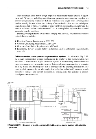
Grid-connected solar power cogeneration system As shown in Fig. 3.37,
the power cogeneration system configuration is similar to the hybrid system just
described. The essence of a grid-connected system is net metering. Standard service
meters are odometer-type counting wheels that record power consumption at a service
point by means of a rotating disk that is connected to the counting mechanism. The
rotating disk operates by an electrophysical principle called eddy current, which
consists of voltage- and current-measurement sensing coils that generate a propor-
tional power measurement.
PV MODULE
TO ADDITIONAL
OVER CURRENT DEVICE INVERTERS
ISOLATION TRANSFORMER
+ − H RECORDING METER
POSITIVE BUS NEGATIVE BUS INVERTER + − H N H N N M
DISCONNECT
NEUTRAL SWITCH
BUS
FUSED DC COLLECTOR LOAD CENTER
MAIN SERVICE SUPPLY
MAIN MAIN
SWITCHGEAR M SERVICE
GROUND
PV FRAME GROUND CONNECTION CONNECTED LOAD
Figure 3.37 Diagram of a grid-connected hybrid solar ac power system with standby
generator.