
Page 221 - Amphibionics : Build Your Own Biologically Inspired Robot
P. 221
Amphibionics 06 3/24/03 9:02 AM Page 200
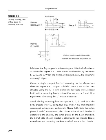
FIGURE 6.9
Cutting, bending, and
drilling guide for Amphibionics
mounting brackets.
Fabricate four leg support brackets using the 1/16-inch aluminum,
as detailed in Figure 6.9. These pieces are identified by the letters
B, C, D, and E. When the pieces are finished, use a file to remove
any rough edges.
Create a single support bracket according to the dimensions
shown in Figure 6.9. This part is labeled piece F, and is also con-
structed using the 1/16-inch aluminum. Fabricate two L-shaped
limit switch mounting brackets identified as pieces G and H in
Figure 6.9, also using the 1/16-inch aluminum.
Attach the leg mounting brackets (pieces B, C, D, and E) to the
body chassis (piece A) using four 6/32-inch 1/2-inch machine
screws and locking nuts, as shown in Figure 6.10. Note that when
pieces B and C are mounted, the 1/4-inch side of each bracket is
attached to the chassis, and when pieces D and E are mounted,
the 1-inch side of each bracket is attached to the chassis. Figure
6.10 shows the mounting brackets attached to the robot chassis.
200