
Page 351 - Amphibionics : Build Your Own Biologically Inspired Robot
P. 351
Amphibionics 07 3/24/03 9:13 AM Page 330
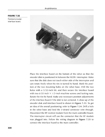
FIGURE 7.32
Finished encoder
interface board. Amphibionics
Place the interface board on the bottom of the robot so that the
encoder disk is positioned in between the H22B1 interrupter. Make
sure that the disk does not touch either side of the interrupter and
can rotate freely when the tire is turned by hand. Mark the posi-
tion of the two mounting holes on the robot base. Drill the two
holes with a 5/32-inch bit, and then secure the interface board
with two 6/32-inch 1/2-inch machine screws and locking nuts.
Rotate the tire by hand. Make any necessary position adjustments
of the interface board if the disk is not centered. A close-up of the
encoder disk and interface board is shown in Figure 7.33. To get
an idea of the overall positioning, refer to Figure 7.34. Drill a hole
in the robot base and feed the 3-strand connector wire through.
Disconnect the RF receiver module from the main controller board.
The interrupter circuit will use the connector that the RF module
was plugged into. Follow the wiring diagram in Figure 7.35 to
connect the interface board to the main controller.
330