
Page 353 - Amphibionics : Build Your Own Biologically Inspired Robot
P. 353
Amphibionics 07 3/24/03 9:13 AM Page 332
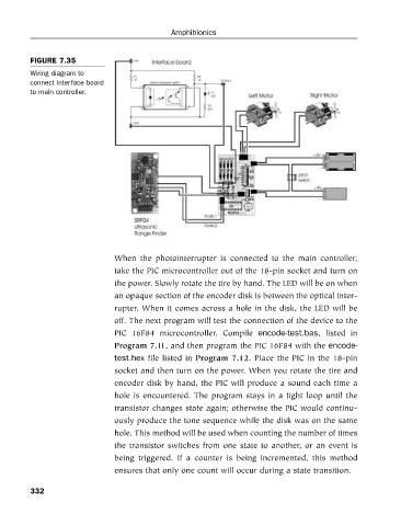
FIGURE 7.35
Wiring diagram to
connect interface board Amphibionics
to main controller.
When the photointerrupter is connected to the main controller,
take the PIC microcontroller out of the 18-pin socket and turn on
the power. Slowly rotate the tire by hand. The LED will be on when
an opaque section of the encoder disk is between the optical inter-
rupter. When it comes across a hole in the disk, the LED will be
off. The next program will test the connection of the device to the
PIC 16F84 microcontroller. Compile encode-test.bas, listed in
Program 7.11, and then program the PIC 16F84 with the encode-
test.hex file listed in Program 7.12. Place the PIC in the 18-pin
socket and then turn on the power. When you rotate the tire and
encoder disk by hand, the PIC will produce a sound each time a
hole is encountered. The program stays in a tight loop until the
transistor changes state again; otherwise the PIC would continu-
ously produce the tone sequence while the disk was on the same
hole. This method will be used when counting the number of times
the transistor switches from one state to another, or an event is
being triggered. If a counter is being incremented, this method
ensures that only one count will occur during a state transition.
332