Page 349 - Amphibionics : Build Your Own Biologically Inspired Robot
P. 349

Amphibionics 07  3/24/03  9:13 AM  Page 328
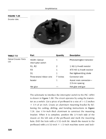
                      FIGURE 7.29
                      Encoder disk.


                      TABLE 7.5           Part         Amphibionics Quantity  Description
                      Optical Encoder Parts
                                          H22B1 Optical          1           Photodarlington transistor
                      List
                                          interrupter switch
                                          R1, R2                 2           1 K  1/4-watt resistor
                                          R3                     1           470 K  1/4-watt resistor
                                          D1                     1           Red light-emitting diode
                                          Three-strand ribbon wire  7 inches  Connector wire
                                          header                 1           4-post male connector—
                                                                             2.5-mm spacing
                                          Hot glue               —           Hot glue and gun


                                          The schematic to interface the interrupter switch to the PIC 16F84
                                          is shown in Figure 7.30. The circuit operates by using the transis-
                                          tor as a switch. Cut a piece of perfboard to a size of 1-1/2 inches
                                            3/4 of an inch. Create an aluminum mounting bracket by fol-
                                          lowing  the  cutting,  drilling,  and  bending  instructions  in  Figure
                                          7.31.  Use  1/16-inch  thick  aluminum  to  construct  the  mounting
                                          bracket.  When  it  is  complete,  position  the  3/4-inch  side  of  the
                                          mount on the left side of the perfboard and mark the mounting
                                          hole. Drill the hole with a 5/32-inch bit. Attach the mount to the
                                          perfboard with a 6/32-inch   1/2-inch machine screw and lock-

                      328
   344   345   346   347   348   349   350   351   352   353   354