
Page 347 - Amphibionics : Build Your Own Biologically Inspired Robot
P. 347
Amphibionics 07 3/24/03 9:13 AM Page 326
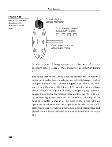
FIGURE 7.27
Optical encoder and
photointerrupter Amphibionics
attached to motor
shaft.
for the purpose of being mounted on either side of a shaft
encoder’s disk, is called a photointerrupter, as shown in Figure
7.27.
The device that we will use to track the distance that Turtletron’s
motor has traveled is a photodarlington optical interrupter switch
with part number H22B1, shown in Figure 7.28. The H22B1 con-
sists of a gallium arsenide infrared LED, coupled with a silicon
photodarlington in a plastic housing. The packaging system is
designed to optimize the mechanical resolution, coupling efficien-
cy, ambient light rejection, cost, and reliability. The gap in the
housing provides a means of interrupting the signal with an
opaque material, switching the output from an “ON” to an “OFF”
state. The interrupter will be mounted on a small circuit board and
placed around the encoder disk that was included with the motor
kits.
326