
Page 104 - An Introduction to Microelectromechanical Systems Engineering
P. 104
Techniques for Sensing and Actuation 83
Table 4.2 Comparison of Various Actuation Methods on the Basis of Maximum Energy Density. Actual
Energy Output May Be Substantially Lower Depending on the Overall Efficiency of the System
Actuation Max. Energy Physical and Estimated Approximate
3
Density Material Parameters Conditions Order (J/cm )
Electrostatic ½ ε E 2 E = electric field 5 V/µm ~ 0.1
0
ε = dielectric permittivity
0
-6
Thermal ½ Y (α∆T) 2 α = coefficient of expansion 3 × 10 /ºC ~ 5
∆T = temperature rise 100ºC
Y = Young’s modulus 100 GPa
2
Magnetic ½ B /µ 0 B = magnetic field 0.1 T ~ 4
µ = magnetic permeability
0
Piezoelectric ½ Y (d E) 2 E = electric field 30 V/µm ~ 0.2
33
Y = Young’s modulus 100 GPa
d = piezoelectric constant 2 × 10 -12 C/N
33
Shape-memory alloy — Critical temperature ~ 10 (from reports
in literature)
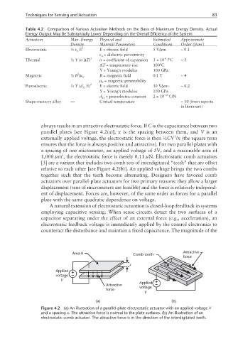
always results in an attractive electrostatic force. If C is the capacitance between two
parallel plates [see Figure 4.2(a)], x is the spacing between them, and V is an
2
externally applied voltage, the electrostatic force is then ½CV /x (the square term
ensures that the force is always positive and attractive). For two parallel plates with
a spacing of one micrometer, an applied voltage of 5V, and a reasonable area of
2
1,000 µm , the electrostatic force is merely 0.11 µN. Electrostatic comb actuators
[3] are a variant that includes two comb sets of interdigitated “teeth” that are offset
relative to each other [see Figure 4.2(b)]. An applied voltage brings the two combs
together such that the teeth become alternating. Designers have favored comb
actuators over parallel-plate actuators for two primary reasons: they allow a larger
displacement (tens of micrometers are feasible) and the force is relatively independ-
ent of displacement. Forces are, however, of the same order as forces for a parallel
plate with the same quadratic dependence on voltage.
A natural extension of electrostatic actuation is closed-loop feedback in systems
employing capacitive sensing. When sense circuits detect the two surfaces of a
capacitor separating under the effect of an external force (e.g., acceleration), an
electrostatic feedback voltage is immediately applied by the control electronics to
counteract the disturbance and maintain a fixed capacitance. The magnitude of the
Area A Comb tooth Attractive
force
x
Applied
voltage
V Applied
Attractive voltage
force
V
(a) (b)
Figure 4.2 (a) An illustration of a parallel-plate electrostatic actuator with an applied voltage V
and a spacing x. The attractive force is normal to the plate surfaces. (b) An illustration of an
electrostatic comb actuator. The attractive force is in the direction of the interdigitated teeth.