
Page 185 - An Introduction to Microelectromechanical Systems Engineering
P. 185
164 MEM Structures and Systems in Photonic Applications
wavelength to the light reflected by this ribbon. Schematically, the corresponding
phasor, ε , rotates in the complex plane by 180º. At the center wavelength, ε , the
m c
phasor corresponding to the compensating ribbon remains in the same orientation
as ε , the phasor for the reference ribbon. The three phasors now add destructively to
r
a null vector [see Figure 5.19(a)] at the center wavelength, and thus light diffracts
into higher orders, causing maximum attenuation of the main undiffracted order. At
a wavelength λ different than λ , the phasor ε rotates by an amount πλ /λ radians
0 m 0
(less or more than π), causing an error vector relative to the phasor at λ . Simultane-
0
ously, the phasor ε rotates by 2Nπλ /λ, causing an error vector in the opposite
c 0
direction—ε rotates past ε by an additional πλ /λ (if N = 1), placing it in an oppo-
c m 0
site quadrant to ε . As the magnitudes of the phasors are proportional to the areas of
m
the ribbons, the two error vectors can be made to cancel each other out under certain
geometrical conditions. Analytical calculations show that if A , A , and A are the
m r c
respective areas of the moveable, reference and compensating ribbons, then there are
two conditions that must be satisfied: A +2A = A and A /A = 1/2N. The first con-
r c m c m
dition ensures equality of the magnitudes of the phasors that are out of phase. The
second condition follows from matching the phases of the error vectors. As a result,
the total phasor is null (ε + ε +ε = 0) over a wide range of wavelengths.
m mr c
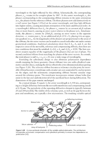
Extending the achromatic design to also eliminate polarization dependence
entails mapping the linear geometry (linear ribbons) into one with cylindrical sym-
metry (circular discs), making the device effectively a two-dimensional phase grating
(see Figure 5.20). The reference ribbon becomes a reference circular post; the move-
able ribbon becomes a membrane with circular cut outs suspended by anchor points
on the edges; and the achromatic compensating ribbons become annular rings
around the reference posts. The membrane incorporates minute release holes that
assist in the fast and uniform removal of the sacrificial layer during fabrication. The
dimensions of the gaps remain unchanged.
In a typical design, N equals 3, the center wavelength is 1,550 nm, correspond-
ing to a height difference between the moveable membrane and compensating annuli
of 2.32 µm. The periodicity of the repeating diffractive element is typically between
20 and 200 µm [42]. The widths of the reference post, as well as the gap between the
post and membrane, are typically a few micrometers. The resulting variable optical
Reflecting membrane
Release holes
Anchor to substrate
λ
d = N 0
2
Silicon substrate
Reflecting surface Achromatic compensator
Array of fixed posts
Figure 5.20 A cross-sectional schematic of the variable optical attenuator. The architecture
incorporates achromatic compensation and cylindrical symmetry to ensure low dependence on
polarization [42].