
Page 184 - An Introduction to Microelectromechanical Systems Engineering
P. 184
Fiber-Optic Communication Devices 163
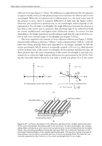
reflected wave [see Figure 5.19(a)]. The difference in angle between the two phasors
is equal to 4πd/λ, where d is the physical separation between the ribbons and λ is the
wavelength. When the two phasors are π radians apart (i.e., the total vector sum of
the phasors is zero), there is complete diffraction of light into the higher orders.
However, this condition is satisfied only at one wavelength, which depends on the
separation d. For all other wavelengths, the angle difference between the phasors is
less than π (the vector sum is nonzero), thus allowing light to be reflected in both
the zeroth (undiffracted) and higher-order diffraction modes. To correct for this
dependence, the design introduces another phasor such that the sum of all three vec-
tors is null over a broad range of wavelengths [see Figure 5.19(a)].
The basic repetitive cell consists of three reflective ribbons [see Figure 5.19(b)]:
one moveable ribbon, a reference “ribbon,” and a compensating “ribbon,” with the
latter two being spatially fixed and separated by an integer multiple of half the
center wavelength (Nλ /2) where λ is typically around 1,550 nm (i.e., their phasors
0 0
will be in phase only at the center wavelength). In the nominal undeflected state, all
three phasors have the same orientations at the center wavelength λ and add con-
0
structively to reflect the light without diffraction (no attenuation by the VOA). Pull-
ing the moveable ribbon down by λ /4 adds a round trip phase of π at the center
0
Im Im
λ
at = λ 0 at λ≠λ 0
ε m πλ o πλ 0
ε m 2ε c λ 2N λ
Re Re
ε r ε r
2ε c
The three phasors add to the null vector ε + ε + ε = 0 for all λ is satisfied when:
c
r
m
A c 1
A + 2 A = A and A m 2N
c
m
r
(a)
ε m ε r Reference ribbon
Moveable ribbon
λ 0 λ
4 N 0
2
ε c ε c
Compensating ribbon
(b)
Figure 5.19 (a) Phasor description of the diffractive operation of the variable optical attenuator.
At the center wavelength, the phasors add to the null vector. At other wavelengths, the compen-
sating ribbon introduces an error vector that cancels the error vector introduced by the moveable
ribbon, thus providing broadband achromatic operation [42]. (b) A schematic illustration of the
achromatic implementation of the variable optical attenuator. The structure consists of groups of
three ribbons, one of which is moveable and two of which are spatially fixed. The latter two are
vertically separated by Nλ /2 where λ is the center wavelength and N is an integer.
0 0