
Page 181 - An Introduction to Microelectromechanical Systems Engineering
P. 181
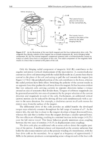
160                                   MEM Structures and Systems in Photonic Applications

                     Mirror structure
                                                              F =  IL×B
                                                                     The Lorentz force is
                                                  F    I             planar to the mirror
                                                           B n
                                                                     for the normal field, B  . n
                              B n                          F


                               B r                              B r
                                                  F =0               The Lorentz force is
                                                                     normal to the plane of the
                             Permanent                  I
                             magnet                      F =  IL×B   mirror for the radial
                                                                     fringing field, B r .
                                                           F =0
                                         Flux lines
                                (a)                       (b)
                 Figure 5.17  (a) An illustration of the rare-Earth magnet and the four independent drive coils. The
                 magnetic flux density outside of the magnet has a normal component, B , and a fringing radial
                                                                        n
                 component, B . (b) The normal magnetic component interacts with a counterclockwise current to
                            r
                 induce a Lorentz force that is in the plane of the coils. The radial component of the magnetic field
                 results in a force that is normal to the plane of the coil.


                    Only the fringing radial component of magnetic field (B ) contributes to the
                                                                         r
                 angular and piston (vertical) displacement of the micromirror. A counterclockwise
                 current in a drive coil interacting with the radial field results in a Lorentz force that is
                 normal to the plane of the coil and acting to pull the coil towards the magnet [see
                 Figure 5.17(b)]—the peripheral portion of the coil contributes to the force, whereas
                 the radial portions have little effect. Switching the polarity of the current results in
                 an opposite force that pushes the coil away from the magnet. It thus becomes evident
                 that two adjacent coils carrying currents in opposite directions induce a torque
                 around an axis of symmetry that divides them. Torques of arbitrary magnitude can
                 be generated around the two axes of symmetry by the proper selection of the current
                 direction and magnitude in each of the coils. Furthermore, an additional vertical
                 (piston) motion can be induced by driving all four coils simultaneously with a cur-
                 rent in the same direction. For example, a clockwise current in all coils moves the
                 mirror away from the surface of the magnet.
                    The differential drive of the coils provides an added benefit: the developed
                 torque stays relatively constant throughout the full range of motion of ±5º. As the
                 mirror tilts, the side that is closer to the magnet develops a larger downward force,
                 whereas the side that is farther from the magnet develops a smaller upward force.
                 The two effects are offsetting, resulting in a minimal increase in the torque (<0.2%)
                 over the full mirror travel. This linear behavior greatly minimizes cross coupling
                 between the two axes of rotation (<0.1% in displacement cross coupling).
                    The drive coils play an additional role as sense coils to detect the angular posi-
                 tion of the mirror. A multiturn planar coil deposited on the ceramic substrate that
                 holds the silicon micromirror acts as the primary winding of a transformer, with the
                 four drive coils as the secondary. An ac signal at a frequency of approximately 5
                 MHz in the primary produces a corresponding sense voltage in each of the four coils