
Page 180 - An Introduction to Microelectromechanical Systems Engineering
P. 180
Fiber-Optic Communication Devices 159
the propagating radiation is in a single Gaussian mode—multimode radiation will
require much larger diameter multiples [38]. The IMMI design micromirror has a
diameter of approximately 3 mm, giving it a mass of 1.7 mg.
The gimbal suspension consists of four serpentine torsional hinges arranged in a
symmetrical topography and formed in the top silicon layer of what conventionally
is the front side of a SOI wafer. This allows the manufacture of thin, compliant
hinges, which results in lower actuation forces [39]. However, if the hinges are too
compliant, the suspension-mirror mechanical system will be sensitive to vibration
and will not survive mechanical shocks. The final dimensions are thus a compro-
mise depending on many factors, including the magnitude of available actuation
forces, required size of the mirror, available real estate, and allowed resonant
modes. The suspension-mirror geometry and dimensions are such that the first reso-
nance of the IMMI mirror is at 140 Hz. The present gimbal suspension favors three
modes of displacement (two out-of-plane angular rotations and one out-of-plane
displacement), but it also permits additional undesirable modes such as in-plane
motion or rotation of the mirror. Fortunately, these undesirable modes have reso-
nant peaks above 3 kHz and thus do not participate in the mirror motion, provided
the control electronics limit the bandwidth to a value lower than these resonant fre-
quencies. Numerical analysis of the suspensions and experimental results has shown
that the rotational spring constants remain unchanged through the full angular dis-
placement of the micromirror. Consequently, the mirror actuation is linear with
current in the drive coils, a feature that simplifies the implementation of the control
electronics.
Magnetic actuation is a key differentiator of the IMMI micromirror, as it deliv-
ers a higher actuation energy per unit volume compared to equivalent electrostatic
actuation methods (see Table 4.2). A larger actuation force enables the use of a rela-
tively stiffer suspension and thicker mirror, thus improving the overall mechanical
response. The actuation force is given by the Lorentz force and depends on the fol-
lowing key parameters: the length and orientation of the drive coil and the intensity
and orientation of the magnetic field vector. The drive coils are formed by electro-
plating on the front side of the wafer with electrical connections leading to tin-lead
(Sn-Pb) solder balls made using standard screen printing and reflow processes. The
solder balls allow the packaging of multiple mirrors in arrays on ceramic substrates
using flip-chip technology (see Chapter 8).
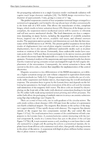
There are a total of four coils, one in each quadrant of the circular mirror. The
coils reside within a short distance (200~500 µm) from the surface of a permanent
rare-Earth cylindrical magnet. The magnetic flux density at the surface of the mag-
net is approximately 1T but rapidly decays with distance. The magnetic flux density
outside of the magnet has two components: normal (B ) and radial (B ) [see
n r
Figure 5.17(a)]. The total actuation force consists of the contributions of both com-
ponents to the Lorentz force. A counterclockwise current interacting with the nor-
mal component B results in a Lorentz force that acts in the plane of the coil [see
n
Figure 5.17(b)]. B is not constant across a coil, resulting in a net force that is radi-
n
ally outward for a single coil. By pairing the coils in a symmetrical manner, the in-
plane forces from all four coils counteract each other, thus greatly reducing motions
in the plane of the mirror. A suspension with high in-plane stiffness further ensures
that in-plane motion is negligible.