
Page 178 - An Introduction to Microelectromechanical Systems Engineering
P. 178
Fiber-Optic Communication Devices 157
three-dimensional (3-D) system architecture using continuously tilting mirrors in
two directions can serve the same functionality but with far fewer mirrors: an opti-
cal cross connect with N input and output fiber ports requires only 2N mirrors. The
mirrors in the 3-D architecture are no longer digital (ON-OFF), but rather point the
light beam from one fiber to another with high spatial precision (see Figure 5.15). In
this beam-steering approach, a first tilting mirror on a first plate points the light
from a collimated input fiber to one of many similar mirrors on a second plate,
which in turn points the light to a collimated output fiber. Both an input and an out-
put mirror are required, so that each can be pointed directly at the centerline of its
corresponding fiber, rather than at an angle. To minimize the maximum angular
displacement of the mirrors, the two plates can be positioned at 45º relative to the
incident light. The angular tilt precision needs be very high. For a system using
single-mode fibers with a typical core diameter of 10 µm and an optical path length
of, say, 10 cm, the mirror must have an accuracy and repeatability of better than
100 µrad (0.006°). The system specifications require a mirror design that is capable
tilting mirrors
Plate with N
N input fibers
N output fibers
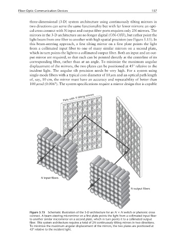
Figure 5.15 Schematic illustration of the 3-D architecture for an N × N switch or photonic cross
connect. A beam-steering micromirror on a first plate points the light from a collimated input fiber
to another similar micromirror on a second plate, which in turn points it to a collimated output
fiber. This system architecture requires a total of 2N continuously tilting mirrors in two directions.
To minimize the maximum angular displacement of the mirrors, the two plates are positioned at
45º relative to the incident light.