
Page 173 - An Introduction to Microelectromechanical Systems Engineering
P. 173
152 MEM Structures and Systems in Photonic Applications
Wavelength (nm)
1,540.545 1,540.386 1,540.228 1,540.070 1,539.912 1,539.753
1.0
Transmission peak
0.9
ITU grid
0.8
)
T(λ 0.7 FSR 1
transmission 0.6 T() = 1 + (2 / ) sin ( λ n )
λ
2 2π d
2
F π
0.5
1/2
πr
Etalon 0.4 Locking F = 1 − r is the finesse
0.3
point
0.2
0.1
0
194.6 194.62 194.64 194.66 194.68 194.7
Frequency (THz)
(a)
Peak-synchronous detection Edge-locking detection
(b)
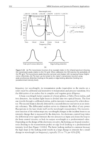
Figure 5.12 (a) The transmission function of an example etalon in the infrared spectrum showing
the transmission peaks relative to the ITU grid. When calibrated, the FSR matches the periodicity of
the ITU grid. The transmission peaks become narrower and sharper with increasing finesse (higher
mirror reflectivity). (b) The laser can be locked to the etalon’s transmission function using
peak-synchronous detection (locking to the peak) or edge-locking detection (locking to a
predetermined intensity level).
frequency (or wavelength), its transmission peaks (equivalent to the marks on a
ruler) must be calibrated and insensitive to temperature and process variations. It is
the fabrication of an etalon that is complex and requires great diligence.
A basic wavelength locker consists of a beam splitter, a Fabry-Perot etalon, and
two detectors. An incident light beam is divided into two optical beams. The first
one travels through a calibrated etalon, and its intensity is measured by a first detec-
tor. The second beam is directly detected by a second detector and serves as an inten-
sity reference. The differential analysis serves to eliminate the effect of any power
fluctuations in the laser diode itself on the wavelength measurement. The transmis-
sion function of the etalon maps any wavelength changes in the incident beam to an
intensity change that is measured by the detectors. An electronic control loop takes
the differential error signal between the two detectors as input and closes the loop to
the laser control circuitry to lock its output wavelength to a predetermined value.
Depending on the design of the electronic circuitry, the locking can be peak synchro-
nous (locking to the transmission peaks) or edge level (locking to a predetermined
intensity level) [see Figure 5.12(b)]. The latter locking method is common because
the high slope at the locking point results in a large change in intensity for a small
change in wavelength (or frequency), typically 2% to 7% per GHz [28].