
Page 170 - An Introduction to Microelectromechanical Systems Engineering
P. 170
Fiber-Optic Communication Devices 149
reflectivity into the cavity. If Λ is the periodicity of a simple grating and n’ is the dif-
ference in indices of refraction of the materials bounding the grating, then the center
wavelength of the grating in free space is Λ/2n' [25]. For a grating centered at 1,550
nm in InP and InGaAsP (n’ 0.2), the required periodicity is approximately 0.6 µm,
necessitating fabrication using high-resolution lithographic tools such as an electron
beam. The dependence of optical gain and index of refraction on temperature
results in the lasing wavelength increasing with temperature at the rate of 0.12
nm/ºC over the range 20º to 80ºC. This is why semiconductor lasers include a TEC
device to control temperature and wavelength.
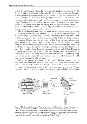
The Santur laser utilizes temperature as the variable parameter to tune the out-
put wavelength of the DFB laser. However, a 25ºC change in temperature results in a
3-nm wavelength shift that is only a fraction of the entire C-Band. This limited ther-
mal tuning range gives rise to using a linear array of 12 DFB lasers. All are similar in
every respect, differing only in the periodicity of their Bragg gratings, each covering a
small portion of the C-Band (about 3 nm) (see Figure 5.10) [26]. Applying a current
to a particular laser in the array selects this laser for operation; a temperature adjust-
ment then fine tunes the output wavelength. A tilting micromachined mirror then
steers the output light beam through a focusing lens into an optical fiber. The micro-
mirror only needs to tilt in one direction for laser selection, but a tilt capability in the
orthogonal direction aids in relaxing the alignment tolerances during final packag-
ing. The maximum angular tilt is quite small, only about ±1.5º, because the DFB
lasers in the array are on a 10-µm pitch.
Unlike the external cavity laser described earlier, this laser resonant cavity is
fully contained within the semiconductor diode, and, hence, external vibrations
have no effect on the output wavelength. However, these external vibrations
may cause minute misalignments of the micromirror relative to the two lenses,
thereby modulating the output power coupled into the optical fiber. Experimental
± 0.5º
Collimating Tilting
+ Bragg lens micromirror
grating
p-InP
±2º
AR coating
n-InP
Waveguide
DFB array Focusing
Single DFB laser (10- m pitch) lens
µ
Fiber
Figure 5.10 Schematic illustration of the tunable array of DFB lasers from Santur Corporation of
Fremont, California. Once a DFB laser in the array is electrically selected, a micromirror steers its
output light through a focusing lens into an optical fiber. Changing the temperature of the DFB
laser array using a TEC device tunes the wavelength over a narrow range. The illustration on the
far left depicts the simplified internal structure of a single DFB laser. Both facets of the
semiconductor diode are coated with an antireflection (AR) coating.