
Page 168 - An Introduction to Microelectromechanical Systems Engineering
P. 168
Fiber-Optic Communication Devices 147
mounting pads forms the reflective mirror end of the cavity. The mirror is 1.7 mm
wide and extends approximately 600 µm above the surface of the actuator. The
maximum range of rotation of the actuator necessary to tune the laser over the
entire C-Band depends on the dispersion of the grating. At 1,200 lines per millime-
ter, one degree of angular rotation at the mirror causes a 7.5-nm shift in wavelength.
Hence, the total required rotation of the actuator is less than five degrees. At this
angle, the distal end of the mirror travels 300 µm.
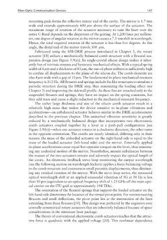
Fabricated using the SFB-DRIE process introduced in Chapter 3, the rotary
actuator [18] utilizes a mechanically balanced comb structure with a flexural sus-
pension design [see Figure 5.9(a)]. Its single-crystal silicon design makes it inher-
ently free of intrinsic stresses and hysteretic mechanical effects. With a typical spring
width of 4 µm and a thickness of 85 µm, the out-of-plane stiffness is sufficiently high
to confine all displacements to the plane of the silicon die. The comb elements are
also 4 µm wide with a gap of 10 µm. The fundamental in-plane mechanical resonant
frequency is 212 Hz. All flexures and springs include fin-like structures to simulate a
periodic structure during the DRIE step, thus minimizing the loading effect (see
Chapter 3) and improving the sidewall profile. As these fins are attached only to the
suspended flexures and springs, they have no impact on the spring constants, but
they add mass and cause a slight reduction in the mechanical resonant frequency.
The rather large thickness and size of the silicon comb actuator result in a
relatively high mass that makes the device sensitive to in-plane vibrations and
accelerations—an unbalanced actuator behaves similar to the DRIE accelerometer
described in the previous chapter. This undesired vibration sensitivity is greatly
reduced by a mechanically balanced design that incorporates two electrostatic
comb actuators coupled together by a lever in a push-pull configuration [see
Figure 5.9(b)]—when one actuator rotates in a clockwise direction, the other turns
in the opposite orientation. The combs are nearly identical, differing only in their
masses: the mass of the unloaded actuator on the right-hand side is equal to the
mass of the loaded actuator (left-hand side) and the mirror. Externally applied
in-plane accelerations cause equal but opposite torques on the lever, thus minimiz-
ing any undesired motion of the mirror. Nonetheless, minute imbalances between
the masses of the two actuators remain and adversely impact the optical length of
the cavity. An electronic feedback servo loop monitoring the output wavelength
(see the following section on wavelength lockers) applies a force-balancing voltage
to the comb structure and counteracts small parasitic displacements, thus eliminat-
ing any residual rotation of the mirror. With the servo loop active, the measured
optical wavelength shift at an applied sinusoidal vibration of 5G at 50 Hz is less
than 10 pm (equivalent to an optical frequency shift of 1.25 GHz off the main opti-
cal carrier on the ITU grid at approximately 194 THz).
The orientation of the flexural springs that support the loaded actuator on the
left-hand side determines the location of the virtual pivot point. For nonintersecting
flexures and small deflections, the pivot point lies at the intersection of the lines
extending from these flexures [19]. This design was preferred by the engineers over
centrally symmetrical rotary actuators that are inherently balanced because of space
considerations in the miniature laser package.
The theory of conventional electrostatic comb actuators teaches that the attrac-
tive force is quadratic with the applied voltage [20]. This nonlinear dependence