
Page 171 - An Introduction to Microelectromechanical Systems Engineering
P. 171
150 MEM Structures and Systems in Photonic Applications
measurements showed that a 10-G shock without compensation by the electronic
control loop caused a small but noticeable 0.2 dB change in output power.
A fully packaged laser contains three electronic control closed-loop circuitries
that use input from a commercial wavelength locker to measure output wavelength
from a 1% optical tap to measure output power in the fiber [11]. The first circuit
controls the drive current to operate one single DFB laser in the array and compen-
sate for any change in the output intensity resulting from long term aging effects. A
second circuit controls the temperature of the DFB laser array, thus tuning the out-
put wavelength. The third circuit applies the appropriate voltages to the micromir-
ror to maximize optical coupling and offset any mechanical misalignment. An
intentional misalignment of the micromirror angle can attenuate the coupled power
into the fiber and turn the mirror into an integrated variable optical attenuator. The
present design offers a 10-dB attenuation range, thus providing an output power
that can be varied from 3 dBm (2 mW) up to 13 dBm (20 mW). It is evident that
when the micromirror is in an extreme angular position, no light couples into the
fiber, thus blanking the laser. This is necessary during the transient duration when
the control electronics are switching between different DFB lasers within the array
or altering the temperature of a single array element.
The final measured specifications of this tunable laser are as follows: the maxi-
mum output power is 13 ± 0.1 dBm tunable from 1,531 to 1,564 nm; the RIN is
lower than –145 dB/Hz up to 10 GHz; the SMSR is 43 dB; and the spectral linewidth
is 8 MHz. The tuning speed of the laser is limited by the response of the TEC to
about 1s. We will discuss the packaging details of this tunable laser in Chapter 8.
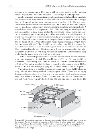
The micromirror is a double-gimbaled structure (see Figure 5.11) fabricated
using bulk-micromachining methods in single-crystal silicon. The mirror is a highly
doped, conductive silicon layer that is a few micrometers thick and is suspended
using torsional flexures from a frame. The inner and outer torsion flexures are 3.5
µm and 5 µm wide, respectively; both are 150 µm long and 15 µm thick. The
Torsional hinge Gold reflector
µ
15 m
Silicon
SiO 2
Silicon
{111} Bond pad
Gold electrodes (at +V)
Glass substrate
Figure 5.11 Schematic cross section of the micromirror used within the tunable laser from Santur
Corporation. The device consists of a double-gimbaled mirror structure supported by torsional
hinges. A gold layer defines the high-reflectivity mirror surface that remains at ground potential.
Four gold electrodes on an anodically bonded glass substrate actuate the mirror and cause
rotation around the hinges.